Both quartz and ceramic materials are used in the production of radio frequency filters. Ceramic filters do not have the same performance as quartz but have the advantages of a lower cost. They are used at lower frequencies and where the higher stability and lower spurious responses of quartz are not essential.
Crystal filters are obtainable at frequencies up to about 45 MHz.
Most of these use either a number of discrete crystals arranged in the form of a lattice or a monolithic structure. A single crystal will behave as an extremely narrow band filter and it is possible to use a crystal bar in this way down to a very few kilohertz.
The characteristics of filters can be divided into groups affecting the performance (Figure 7.7).F0 0 dB
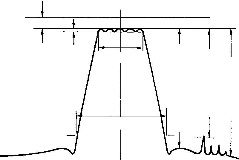 Figure 7.7 Filter characteristics
• Insertion loss. The loss at centre frequency, in dB, resulting from the insertion of the filter in a transmission system.
• Flat loss. The insertion loss at the frequency of minimum loss within the passband.
• Attenuation. The loss of a filter at a given frequency measured in dB.
• Passband (bandwidth, BW1). The range of frequencies attenuated less than a specified value, typically 3 or 6 dB.
• Centre frequency (f0). The arithmetic mean of the passband limits.
• Fractional bandwidth. A specified frequency, typically the minimum loss point or F0, from which all attenuation measurements are made.
• Ripple. The amplitude difference, in dB, between the maximum peak and minimum passband valley. Both the peak and the valley are defined by a surrounding change in slope, i.e. sign of the amplitude response. This is very important as a high ripple, particularly between a peak and the adjacent trough, produces rapid phase changes as the signal moves across the passband resulting in audio distortion and corruption in digital signals.
• Attenuation. The output of a filter at a given frequency relative to the defined insertion loss reference.
• Stopband. The range of frequencies attenuated by a greater amount than some specified minimum level of attenuation.
• Transition band (bandwidth, BW2). The range of frequencies differently attenuated between the passband and stopband limits.
• Shape factor. The ratio of the bandwidth at some point within the transition region, typically 60 dB, to the specified passband bandwidth. It is given by:
Shape factor
BW2
BW1
• Spurious attenuation. The specified minimum level of attenuation received by all non-harmonic related resonances of each crystal resonator within the filter network.
Insertion phase . The phase shift at the output load (measured•
at the reference frequency) resulting from the insertion of the filter.
• Differential phase. The measurement of phase at a given frequency relative to the phase at the reference frequency.
• Phase linearity. The phase error in degrees between the phase points and a straight line drawn through the phase points.
• Group delay. The time by which a signal will be delayed before it appears at the filter output, i.e. the derivative of phase with respect to frequency.
• Differential delay. The measurement of delay at a given frequency relative to the reference frequency.
Source impedance . The impedance of the circuit driving the•
filter, measured at the reference frequency.
• Load impedance. The impedance of the circuit terminating the filter at its output, measured at the reference frequency.
Maximum input level . The driving point power, voltage or cur•
rent level above which intolerable signal distortion or damage to the device will result.
• Drive level stability. The ability of the filter to return within a specified tolerance of its original insertion loss, at a specified drive level, after experiencing changing environmental and/or drive level conditions.
• Drive level linearity. The maximum permissible variation in insertion loss, per dB change in drive level, measured over a specific dynamic range.
• Inband intermodulation distortion. The attenuation, in dB, of third and higher order signal products, inband, relative to the power level of two signals placed within the passband.
• Out-of-band intermodulation distortion. The attenuation, in dB, of third and higher order signal products, inband, relative to the power level of two signals placed in the stopband, or one signal in the transition region and the other in the stopband.
Table 7.1 Manufacturers’ specifications for two stock 10.7 MHz filters Centre Passband Attenuation Ripple Ins. Term. freq. width bandwidth (max) loss impedance (plus/minus) (max) S/pfd