The piezo-electric effect that some ceramic materials such as lithium niobate exhibit enables useful applications, such as pressure sensors and audible alarms. When piezo-electric material has an electric field applied across it, usually through metal electrodes, the material changes shape. This often takes the form of local material expansion or contraction (depending on the polarity of the applied voltage). In the case of the audible alarm, the material expansion and contraction modulates the air pressure to give an audible tone if the electric field is alternating at audio frequencies.
One form of the piezo-electric effect is the SAW (surface-acousticwave) phenomenon, in which signals travel due to an acoustic wave in the ceramic material. To see this effect the piezo-electric material has one side bonded to a metal plate. The upper surface has metal electrodes applied to it, to provide an electric energizing force. The surface wave is created when a material is forced to expand (by the piezoelectric effect) beneath the metal electrodes. Physical bonds between molecules then force adjacent material to expand and this expansion propagates through the material.
The piezo-electric effect is bi-directional, so that if the material between electrodes changes shape, an electric field is generated between the electrodes. This is the effect seen when a piezo-electric gas lighter is used: a sudden force across a piezo-electric element generates high voltages that force a spark to be produced. In the SAW device, the acoustic wave travels along the material and deforms the piezo-electric material between a second set of electrodes, which are located at the other end of the piezo-electric material. A voltage is then formed between these electrodes. By having two sets of electrodes, known as transducers, at opposite ends of a piece of piezo-electric material, a signal can be transmitted through the material by applying a voltage at one end and detecting it at the other.
The range of frequencies that propagate through the piezo-electric material can be controlled by suitable transmit and receive transducer spacing. The propagation frequencies can be further controlled by applying additional metallized areas (described later) between the transmit and receive transducers. Thus SAW devices could be used to make compact and low-cost filters.
SAW resonators use piezo-electric material that is free to vibrate in one direction. The speed of wave propagation and the dimensions of the material are such that the wave reflects back and forth, resonating at a certain frequency. This can replace quartz crystals in many oscillator circuits, where the frequency accuracy is not critical.
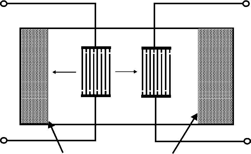
In its simplest form, a transversal SAW filter consists of two transducers with inter-digital arrays of thin metal electrodes deposited on a piezoelectric substrate, such as quartz or lithium niobate (see Figure 7.8). The electrodes that comprise these arrays are arranged to have alternate polarities, so that an RF signal voltage of the proper
0 dB −6 dB
 Acoustic absorber
frequency applied across them causes the surface of the crystal to alternately expand and contract along its length. This generates the Rayleigh wave, or surface wave, as it is more commonly called.
These inter-digital electrodes are generally spaced at half or quarter wavelength of the operating centre frequency. Since the surface wave or acoustic velocity is 105 slower than the speed of light, an acoustic wavelength is much smaller than its free space electromagnetic counterpart. For example, a CW signal at 1000 MHz with a free space wavelength of 300 mm would have a corresponding acoustic wavelength of about 3µm. This wavelength compressing effect results in the SAW filter’s unique ability to provide considerable signal processing or delay in a very small volume.
The wavelength compressing effect of the piezo-electric material has the effect of producing physical limitations at very high and low frequencies. At very high frequencies the electrodes become too narrow to fabricate with standard photo-lithographic techniques. At low frequencies the devices become impracticably large. Consequently, SAW devices are most typically used over the frequency range 10 MHz to about 3 GHz.
The basic SAW transducer is a bi-directional radiator. That is, half of the power (or −3 dB) is directed towards the output transducer while the other half is radiated towards the end of the crystal and is lost. By reciprocity, only half of the intercepted acoustic energy at the output is reconverted to electrical energy; hence, the inherent 6 dB loss associated with this structure (refer to Figure 7.8). Numerous second-order effects, such as coupling efficiency, resistive losses, and impedance mismatch, raise the insertion loss of practical filters to about 15 to 30 dB.
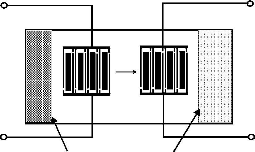
A new low-loss structure is the single-phase unidirectional transducer (SPUDT). Unlike the traditional three-phase unidirectional filters, the SPUDT devices are generally as straightforward to fabricate as ordinary bi-directional transducers. In addition, the required impedance matching network is greatly simplified, usually consisting of an L-C network on each port. Most SPUDT structures contain acoustic reflectors within the inter-digital pattern, illustrated schematically in Figure 7.9 as wider electrodes. These internal reflectors serve to redirect most of the acoustic energy that is normally lost in a conventional bi-directional device. Second-order effects tend to limit the practical insertion loss to about 5 to 12 dB.
0 dB −1 to −3 dB
 Acoustic absorber
A better understanding of SAW device operation can be obtained by understanding how they are designed. SAW filters use finite impulse response design techniques, which are very similar to those used for digital filters. Hence, the Fourier transform is used to relate the time and frequency responses of the transducers and resultant filter. The desired total frequency response characteristics are used to find the impulse responses for the two transducers. These two impulse response shapes are then etched onto the surface of a metallized piezo-electric substrate to form transducers. When an impulse is applied to the transducer, the output wave shape is the same as the shape of the metallized transducer pattern.
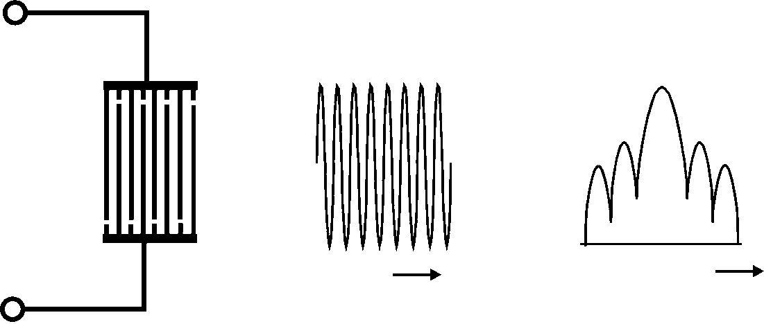
To illustrate this relationship, the following examples may be valuable. First, consider the case of the uniform-overlap (or unweighted) transducer as shown in Figure 7.10. Since all fingers have the same
 Time Frequency
Figure 7.10 Uniform-overlap transducer Frequency response
length, the impulse response envelope of this transducer is a rectangle. The Fourier transform of a rectangle is a sin(x)/x function with a 4 dB bandwidth roughly equal to the reciprocal of its time length. This illustrates the important trade-off between bandwidth and size, the narrower the bandwidth: the longer the transducer.
The sin (x)/x response has 13 dB first side-lobe attenuation, which results in 26 dB of rejection when two of these unweighted transducers are cascaded on the substrate. The 26 dB frequency rejection and poor skirt selectivity make the unweighted transducer suitable for delay lines, but unsuitable for most filter applications where more rejection is needed close to the passband edge.
According to Fourier transform theory, to obtain the rectangular frequency response, a transducer must be built that is infinitely long with electrode lengths that have sin(x)/x weighting. This is impossible, but the principle behind this example will always hold true: the steeper the skirts (the more rectangular the response) for a given bandwidth, the longer the device must be. The longest possible SAW device would exhibit a narrow bandwidth with a very steep roll-off. The transducer pattern must be limited in length but a gradual tailing off to zero length of the outer electrodes provides close to ideal performance (akin to the windowing function in digital FIR filters).