International Journal of Engineering Science Invention
ISSN (Online): 2319 – 6734, ISSN (Print): 2319 – 6726
www.ijesi.org Volume 3 Issue 7ǁ July 2014 ǁ PP.11-17
 Design and Electromagnetic Modeling of E-Plane Sectoral Horn Antenna For Ultra Wide Band Applications On WR-137 & WR-62 Waveguides
S.Srinath
(Final Year Student,ECE, Vellore Institute of Technology, Vellore, India)
ABSTRACT : The Design and EM modeling of a E-Plane Sectoral Horn Antenna for Ultra Wide Band Application on WR-137 and WR-62 standard waveguides are presented in this paper. In E-plane sectoral antenna, the E-Plane is much narrower as the flaring and dimensions of the horn are much greater in that direction. The horn flare angle, horn size, wall thickness, etc of the E-plane sectored horn antenna are examined. The return loss, input impedance, total gain and field pattern of the E-plane sectored horn antenna are observed. The antenna is simulated using ANSOFT HFSS 14.0.
KEYWORDS : Ansoft HFSS Simulator, Beam width, Directivity, E-Plane Horn Antenna, Electromagnetic modeling, Radiation Pattern, Return Loss
I. INTRODUCTION
An antenna is an electrical device which converts electric currents into radio waves, and vice versa. To transmit the signal a transmitter applies an oscillating radio frequency electric signal to the antenna’s terminals, and the antenna radiates the energy in the form of electromagnetic waves.Horn antennas are used as antennas at UHF and microwave frequencies, above 300 MHz. They are used as feeders for larger antenna structures such as parabolic antennas. Over the hundred years, horn antennas have given the best directive and high power operation for Microwave Frequencies. Design Simplicity and large gain with best matching properties are added advantage of Horn antenna. Applications include Radar, Satellite tracking, Radio astronomy and Communication dish antennas. Other applications are Reflector feeds, Gain standards for antenna measurements, EMC/EMI tests, Communication systems, Direction finding (DF), mm-wave systems.

Fig 1 : A Practical Horn Antenna
A E-plane sectoral horn is one in which the opening is flared in the direction of the E-field.
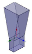
Fig 2 : E-Sectored Horn Antenna
The E-Plane sectored horn antennas are chosen because of their directional radiation pattern, ability to achieve high gain and directivity, and their ease of fabrication. The horn antenna which is designed was subject to the following constraints:
II. ANTENNA DESIGN
The C and Ku frequency bands were selected as the operating frequency. These bands are selected as they pertain to the communication frequency bands. The design was performed to accomplish an ultra-wide bandwidth. (i) For the first case of 8Ghz (C Band) the operating frequency was chosen to be 8Ghz. The waveguide dimensions are a = 34.85mm, b = 15.8mm, waveguide length = 31.75mm. These indicate the standard WR-137 waveguide. Horn size dimensions are b=44.45mm, horn flare length = 95.25mm, wall thickness = 1.626mm. (ii) For the second case of 16Ghz (Ku Band) the operating frequency was chosen to be 16Ghz. The waveguide dimensions are a = 15.8mm, b = 7.9mm, waveguide length = 15.88mm. These indicate the standard WR-62 waveguide. Horn size dimensions are b=22.23mm, horn flare length = 47.63mm, wall thickness = 1.016mm. For both the cases the outer boundary condition is Radiation Boundary Condition. The Radiation Boundary Condition are as follows :
 from strongly radiating structure
 from weakly radiating structure
In HFSS to properly model the far field behavior of an antenna, an appropriate volume of air must be included in the simulation. Truncation of the solution space is performed by including a radiation boundary condition on the faces of this air volume that mimics free space. The appropriate distance between strongly radiating structures and the nearest face of the air volume depends upon whether a radiation boundary condition is used. HFSS also uses Finite Element Method (FEM) as analysis & solution to Electromagnetic problems by developing technologies such as tangential vector finite elements, adaptive meshing, and Adaptive Lanczos- Pade Sweep (ALPS).
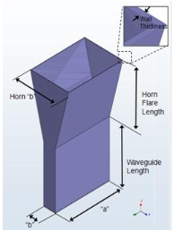
Fig 3 : Structure of the proposed E-Plane Horn Antenna
III. PROPOSED MODEL IN ANSOFT HFSS 14.0 FOR CASE 1
The 3D view of the designed E-Plane Horn Antenna in HFSS for a solution frequency of 8Ghz (C- Band ) is shown below. The boundaries for the air-box are set as an ideal propagation space and and the ground plane as perfect electric conductor.
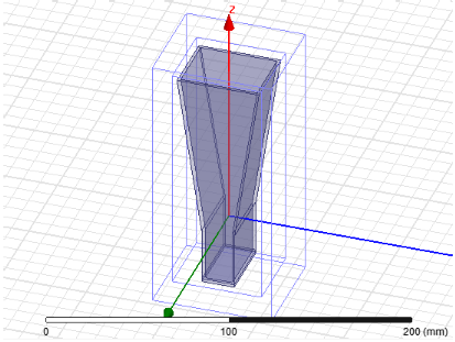
Fig 4 : 3D View of the E-Plane Horn antenna in HFSS for a solution frequency of 8Ghz
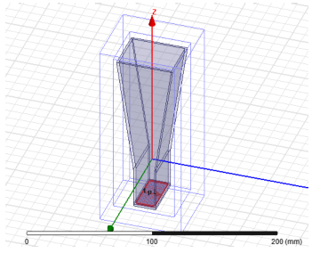
Fig 5 : Figure showing the direction of excitation for a solution frequency of 8Ghz
IV. RESULTS AND DISCUSSION FOR CASE 1
The parameters which verify the success of antenna design are beam width, impedance matching ,