Design of 4th Order Parallel Coupled Microstrip Bandpass Filter at Dual Frequencies of 1.8 GHz and 2.4 GHz for Wireless Application
S.Srinath
UG Student, Dept. Of ECE, Vellore Institute Of Technology, Vellore, Tamilnadu, India
ABSTRACT: Design of a parallel-coupled microstrip bandpass filter is presented in this paper. The aim of this paper is to present the design technique, parameter analysis, real prototype fabrication and measurement results at dual simulation frequencies of 1.8GHz and 2.4GHz. Half wavelength long resonators and admittance inverters are used to design the filter. The filter is simulated using AWR Microwave Office software (Advanced Wave Research).
KEYWORDS: Bandpass filter; Microstrip; 1.8 GHz & 2.4GHz; Parallel Coupled Line; Microwave Engineering; AWR Simulator.
I.INTRODUCTION
The microwave filter is a two port network which used to control the frequency response by providing transmission at frequencies within the passband and attenuation in the stopband of a filter. Filters are an essential part of telecommunications and radar systems. Of its low-cost fabrication, easy integration and simple designing procedure, the parallel coupled-line/edge-coupled filters are widely used in microwave microstrip circuits with a required bandwidth up to 20 % of central frequency . A bandpass filter only passes the frequencies within a certain desired band and attenuates others signals whose frequencies are either below a lower cutoff frequency or above an upper cut-off frequency. The range of frequencies that a bandpass filter let’s to pass through is referred as passband. A typical bandpass filter can be obtained by combining a low-pass filter and a high-pass filter or applying conventional low pass to bandpass transformation . The architecture demonstrated here is a coupled line type filter, since this is among the most practical and common filter types which can meet the stated specifications. In Coupled Transmission Lines, coupling between two transmission lines is introduced by their proximity to each other. Coupling effects may be undesirable, such as crosstalk in printed circuits, or they may be desirable, as in directional couplers where the objective is to transfer power from one line to the other . Another of their major use is using them in filtering the Microwave range frequencies.
The filter response will be based on the Chebychev transfer function. Chebychev type filters are popular for their high selectivity, i.e., they have a relatively fast signal cut off between pass and stop band. Filters operating in gigaherz frequency ranges rely on distributed transmission line structures to obtain the desired frequency response. Dimensions of the coupled transmission lines can be derived with published formula or minimal simulation software capability.
II.RELATED WORK
This paper presents the design of a parallel-coupled microstrip bandpass. The design is based on the use of half wave long resonators and admittance inverters. The dual center frequencies of 1.8 GHz & 2.4GHz are selected, the bandwidth (BW) is about 5%, the minimum attenuation amounts to -30 dB and the pass-band ripple is obtained equal to 0.5 dB.The design technique, parameter analysis, real prototype fabrication and measurement results of a 4th order coupled line bandpass filter at a dual simulation frequencies of 1.8GHz & 2.4GHz is presented in this paper.
III. THEORY
A general layout of a parallel coupled microstrip bandpass is shown in figure 3.1 . The filter structure consists of open circuited coupled microstrip lines . These coupled lines are quarter wavelength , (λ/4) long and are equivalent to shunt resonant circuits. The coupling gaps correspond to the admittance inverters in the low-pass prototype circuit. Even- and odd- mode characteristic impedances of parallel-coupled half-wave resonators are computed using admittance inverters. These even- and odd- mode impedances are then used to compute physical dimensions of the filter. Now consider a bandpass filter composed of a cascade of N + 1 coupled line sections, as shown in Figure 3.1. The sections are numbered from left to right, with the load on the right, but the filter can be reversed without affecting the response. Since each coupled line section has an equivalent circuit of the form, the equivalent circuit of the cascade is as shown in Figure 3.2.
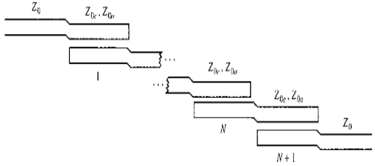
Figure 3.1 : Layout of an (N + 1)-section coupled line bandpass filter.
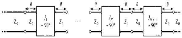
Figure 3.2 : Using the equivalent circuit of Figure 3.1 for each coupled line section.
IV. IMMITANCE INVERTER
Immittance inverters play a very important role in filter design. They are used to transform a filter circuit into an equivalent form that can be easily implemented using various microwave structures. Immittance inverters are either impedance or admittance inverters. Making use of the properties of immittance inverters, bandpass filters may be realized by series (L-C) resonant circuits separated by impedance inverters (K) or shunt (L-C) parallel resonant circuits separated by admittance inverters (J). To design a bandpass filter, first of all a low-pass prototype circuit is modified to include immittance inverters. These low pass structures are then converted to bandpass circuits by applying conventional low-pass to bandpass transformation.
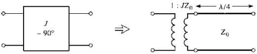
Figure 4.1 : Equivalent circuit of the admittance inverters.
V.SIMULATION MODELING AND DISCUSSION
The design equa