the valve element. A poppet-type valve is usually hydraulically operated. A rotary-spool
type may be manually (lever or plunger action), mechanically (cam or trip action), or electrically (solenoid action) operated. A sliding-spool type may be manually, mechanically, electrically, or hydraulically operated, or it may be operated in combination.
Directional-control valves may also be classified according to the number of positions of
the valve elements or the total number of flow paths provided in the extreme position. For
example, a three-position, four-way valve has two extreme positions and a center or neutral
position. In each of the two extreme positions, there are two flow paths, making a total of
four flow paths.
Spool valves (see Figure 5-11) are popular on modern hydraulic systems because they—
•
Can be precision-ground for fine-oil metering.
•
Can be made to handle flows in many directions by adding extra lands and oil
ports.
•
Stack easily into one compact control package, which is important on mobile sys-
tems.
Spool valves, however, require good
maintenance. Dirty oil will damage the
mating surfaces of the valve lands, causing
them to lose their accuracy. Dirt will cause
these valves to stick or work erratically.
Also, spool valves must be accurately
machined and fitted to their bores.
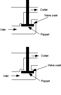
a. Poppet Valve. Figure 5-12, page 5-10,
shows a simple poppet valve. It consists
primarily of a movable poppet that closes
against a valve seat. Pressure from the
inlet tends to hold the valve tightly closed.
A slight force applied to the poppet stem
opens the poppet. The action is similar to
the valves of an automobile engine. The
poppet stem usually has an O-ring seal to
prevent leakage. In some valves, the pop-
pets are held in the seated position by
springs. The number of poppets in a valve
depends on the purpose of the valve.
Figure 5-11. Spool valve
Valves
5-9
FM 5-499
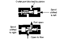
b. Sliding-Spool Valve. Figure 5-13 shows a
sliding-spool valve. The valve element slides back
and forth to block and uncover ports in the housing.
Sometimes called a piston type, the sliding-spool
valve has a piston of which the inner areas are equal.
Pressure from the inlet ports acts equally on both
inner piston areas regardless of the position of the
spool. Sealing is done by a machine fit between the
spool and valve body or sleeve.
Figure 5-12. Operation of a sim-
Figure 5-13. Operation of sliding-spool,
ple poppet valve
directional-control valve
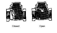
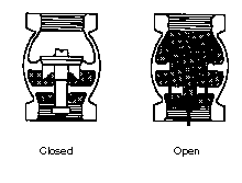
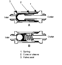
c. Check Valves. Check valves are the most commonly used in fluid-powered systems.
They allow flow in one direction and prevent flow in the other direction. They may be
installed independently in a line, or they may be incorporated as an integral part of a
sequence, counterbalance, or pressure-reducing valve. The valve element may be a sleeve,
cone, ball, poppet, piston, spool, or disc. Force of the moving fluid opens a check valve; back-flow, a spring, or gravity closes the valve. Figures 5-14, 5-15 and 5-16 show various types of check valves.
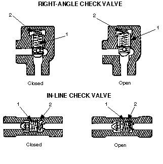
(1) Standard Type (Figure 5-17, page 5-12). This valve may be a right-angle or an in-
line type, depending on the relative location of the ports. Both types operate on the same
principle. The valve consists essentially of a poppet or ball 1 held on a seat by the force of spring 2. Flow directed to the inlet port acts against spring 2 to unseat poppet 1 and open
the valve for through flow (see Figure 5-17, diagram B, for both valve types). Flow entering the valve through the outlet port combines with spring action to hold poppet 1 on its seat to check reverse flow.
These valves are available with various cracking pressures. Conventional applications
usually use the light spring because it ensures reseating the poppet regardless of the valve's 5-10
Valves
FM 5-499
mounting position. Heavy
spring units are generally used
to ensure the availability of at
least the minimum pressure
required for pilot operations.
(2) Restriction Type (Fig-
ure 5-18, page 5-12). This
valve has orifice plug 1 in the
nose of poppet 2, which makes
it different from a conven-
tional, right-angle check valve.
Flow directed to the inlet port
opens the valve, allowing free
Figure 5-14. Swing-type check valve
flow through the valve.
Reverse flow directed in through
the outlet port seats poppet 2.
Flow is restricted to the amount
of oil, which can be altered, to
allow a suitable bleed when the
poppet is closed. Uses of a
restriction check valve can be to
control the lowering speed of a
down-moving piston and the
rate of decompression in large
presses.
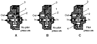
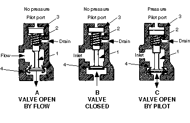
(3) Pilot-Operated Type
(Figure 5-19, page 5-13). In dia-
gram A, the valve has poppet 1
Figure 5-15. Vertical check valve
seated on stationary sleeve 2 by
spring 3. This valve opens the same as a
conventional check valve. Pressure at the
inlet ports must be sufficient to overcome
the combined forces of any pressure at the
outlet port and the light thrust of spring 3
so that poppet 1 raises and allows flow
from the inlet ports through the outlet
port. In this situation, there is no pressure
required at the pilot port.
In diagram B, the valve is closed to
prevent reverse flow. Pressure at the out-
let port and the thrust of spring 3 hold pop-
pet 1 on its seat to block the flow. In this
case, the pilot port has no pressure.
In diagram C, pressure applied at the
pilot port is sufficient to overcome the
thrust of spring 3. The net forces exerted
Figure 5-16. Spring-loaded check valve
Valves
5-11
FM 5-499
A
B
Figure 5-17. Standard check valve
Figure 5-18. Restriction check valve
5-12
Valves
FM 5-499
Figure 5-19. Pilot-operated check valve
by pressures at the other ports raise piston 4 to unseat poppet 1 and allow controlled flow
from the outlet to the inlet ports. With no pressure at the inlet ports, pilot pressure must exceed 40 percent of that imposed at outlet to open the poppet.
Figure 5-20 shows another pilot-operated check valve. This valve consists of poppet 1
secured to piston 3. Poppet 1 is held against seat 4 by the action of spring 2 on piston 3. In diagram A, the valve is in the free-flow position. Pressure at the inlet port, acting downward against poppet 1, is sufficient to overcome the combined forces of spring 2 against piston 3
and the pressure, if any, at the outlet port. (The pressure at the outlet port is exerted over a greater effective area than that at the inlet because of the poppet stem.) The drain post is open to the tank, and there is no pressure at the pilot port. Diagram B shows the valve in a position to prevent reverse flow, with no pressure at the pilot port and the drain opening to the tank.
Figure 5-20. Pilot-operated check valve, second type
Valves
5-13
FM 5-499
Diagram C shows the pilot operation of the valve. When sufficient pressure is applied at
the pilot port to overcome the thrust of spring 2 plus the net effect of pressure at the other ports, poppet 1 is unseated to allow reverse flow. Pilot pressure must be equal to about 80
percent of that imposed at the outlet port to open the valve and allow reverse flow.
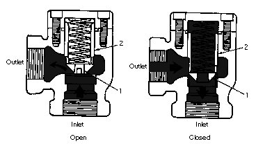
d. Two-Way Valve. A two-way valve is generally used to control the direction of fluid flow in a hydraulic circuit and is a sliding-spool type. Figure 5-21 shows a two-way, sliding-spool, directional-control valve. As the spool moves back and forth, it either allows or prevents fluid flow through the valve. In either shifted position in a two-way valve, a pressure port is open to one cylinder port, but the opposite cylinder port is not open to a tank. A tank port on this valve is used primarily for draining.
e. Four-Way Valves. Four-way, directional-control valves are used to control the direction of fluid flow in a hydraulic circuit, which controls the direction of movement of a work cylinder or the rotation of a fluid motor. These valves are usually the sliding-spool type. A typical four-way, directional-control valve has four ports:
•
One pressure port is connected to a pressure line.
•
One return or exhaust port is connected to a reservoir.
•
Two working ports are connected, by lines, to an actuating unit.
Four-way valves consist of a rectan-
gular cast body, a sliding spool, and a way
to position a spool. A spool is precision-
fitted to a bore through the longitudinal
axis of a valve’s body. The lands of a spool
divide this bore into a series of separate
chambers. Ports in a valve’s body lead
into a chamber so that a spool's position
determines which ports are open to each
other and which ones are sealed off from
each other. Ports that are sealed off from
each other in one position may be inter-
connected in another position. Spool posi-
tioning is accomplished manually,
mechanically, electrically, or hydrauli-
cally or by combing any of the four.
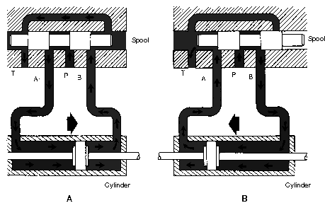
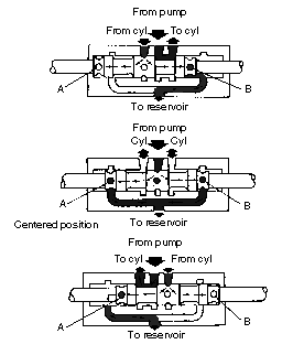
Figure 5-22 shows how the spool posi-
tion determines the possible flow condi-
tions in the circuit. The four ports are
marked P, T, A, and B: P is connected to
the flow source; T to the tank; and A and
B to the respective ports of the work cylin-
der, hydraulic motor, or some other valve
in the circuit. In diagram A, the spool is
in such a position that port P is open to
port A, and port B is open to port T. Ports
Figure 5-21. Two-way valve
A and B are connected to the ports of the
cylinder, flow through port P, and cause
5-14
Valves
FM 5-499
Figure 5-22. Flow conditions in a circuit
the piston of the cylinder to move to the right. Return flow from the cylinder passes through ports B and T. In diagram B, port P is open to port B, and the piston moves to the left.
Return flow from the cylinder passes through ports A and T.
Table 5-1, page 5-16, lists some of the classifications of directional-control valves. These valves could be identified according to the—
•
Number of spool positions.
•
Number of flow paths in the extreme positions.
•
Flow pattern in the center or crossover position.
•
Method of shifting a spool.
•
Method of providing spool return.
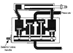
(1) Poppet-Type Valve. Figure 5-23, page 5-16, shows a typical four-way, poppet-type,
directional-control valve. It is a manually operated valve and consists of a group of conventional spring-loaded poppets. The poppets are enclosed in a common housing and are inter-
connected by ducts so as to direct the fluid flow in the desired direction.
The poppets are actuated by cams on the camshaft. They are arranged so that the
shaft, which is rotated by its controlling lever, will open the correct poppet combinations to direct the fluid flow through the desired line to the actuating unit. At the same time, fluid will be directed from the opposite line of the actuating unit through the valve and back to the reservoir or exhausted to the atmosphere.
Valves
5-15
FM 5-499
Table 5-1. Classifications of directional-control valves
Classification
Description
Path-of-flow type
Two way
Allows a total of two possible flow paths in two
extreme spool positions
Four way
Allows a total of four possible flow paths in two
extreme spool positions
Control type
Manual operated
Hand lever is used to shift the spool.
Pilot operated
Hydraulic pressure is used to shift the spool.
Solenoid action is used to shift the spool.
Solenoid operated
Solenoid action is used to shift the integral pilot
Solenoid controlled, pilot oper-
spool, which directs the pilot flow to shift the main
ated
spool.
Position type
Two position
Spool has two extreme positions of dwell.
Spool has two extreme positions plus one interme-
Three position
diate or center position.
Spring type
Spring offset
Spring action automatically returns the spool to the
normal offset position as soon as shifter force is
released. (Spring offset is always a two-way
No spring
valve.)
Spool is not spring-loaded; it is moved only by
shifter force, and it remains where it is shifted (may
be two- or three-position type, but three-position
Spring centered
type uses detent).
Spring action automatically returns the spool to the
center position as soon as the shifter force is
released. (Spring-centered is always a three-
position valve.)
Spool type
Open center
These are five of the more common spool types.
Closed center
They refer to the flow pattern allowed when the
Tandem center
spool is in the center position (three-position
Partially closed center
valves) or in the cross-over position (two-position
Semi-open center
valves).
Springs hold the poppets to their
seats. A camshaft unseats them to
allow fluid flow through the valve.
The camshaft is controlled by moving
the handle. The valve is operated by
moving the handle manually or by
connecting the handle, by mechanical
linkage, to a control handle. On the
camshaft are three O-ring packings
to prevent internal and external leak-
age. The camshaft has two lobes
(raised portions). The contour
(shape) of these lobes is such that
when the shaft is placed in the neu-
tral position, the lobes will not touch
any of the poppets.
Figure 5-23. Working view of poppet-type, four-
way valve
5-16
Valves
FM 5-499
One cam lobe operates the two pressure poppets; the other lobe operates the two return/
exhaust poppets. To stop the rotating camshaft at the exact position, a stop pin is secured to the body and extended through a cutout section of the camshaft flange. This stop pin prevents overtravel by ensuring that the cam lobes stop rotating when the poppets have
unseated as high as they can go.
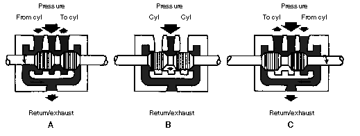
Figure 5-23 shows a working view of a poppet-type, four-way valve. The camshaft
rotates by moving the control handle in either direction from neutral. The lobes rotate,
unseating one pressure poppet and one return/exhaust poppet. The valve is now in a work-
ing position. Pressure fluid, entering the pressure port, travels through the vertical fluid passages in both pressure poppet seats. Since only one pressure poppet is unseated by the
cam lobe, the fluid flows past the open poppet to the inside of the poppet seat. It then flows out one working port and to the actuating unit. Return fluid from the actuating unit enters
the other working port. It then flows through the diagonal fluid passages, past the unseated return poppet, through the vertical fluid passages, and out the return/exhaust port. By
rotating the camshaft in the opposite direction until the stop pin hits, the opposite pressure and return poppets are unseated, and the fluid flow is reversed. This causes the actuating
unit to move in the opposite direction.
(2) Sliding-Spool Valve. The four-way, sliding-spool, directional-control valve is simple
in operation principle and is probably the most durable and trouble free of all four-way,
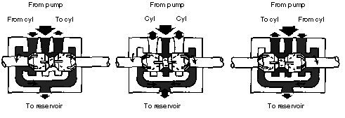
directional-control valves in current use. Figure 5-24 shows a typical four-way, sliding-
spool, directional-control valve. The valve body contains four fluid ports: pressure, return/
exhaust, and two working ports (referred to as cylinder ports). A hollow steel sleeve fits into the main bore of the body. Around the outside diameter of the sleeve are O-ring gaskets.
These O-rings form a seal between the sleeve and the body.
In Figure 5-24, diagram A, the valve is at the far right in its cylinder. Liquid from the
pump flows to the right end of the cylinder port, while liquid from the left end returns to the reservoir. In diagram C, the situation is reverse. The piston is to the far left in its cylinder.
Liquid from the pump flows to the left end of the cylinder port, while liquid from the right
end returns to the reservoir. In diagram B, the piston is in an intermediate position. Flow through the valve from the pump is shut off, and both ends of the cylinder can drain to the
Figure 5-24. Schematic of a four-way, directional-control, sliding-spool valve
Valves
5-17
FM 5-499
reservoir unless other valves are set to control the flow.
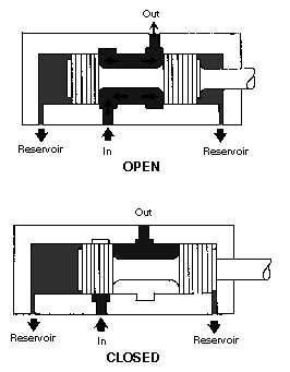
In a closed-center spool valve, a piston is solid, and all passages through a valve are blocked when a piston is centered in its cylinder (see Figure 5-24, diagram B). A closed-center valve is used when a single pump or an accumulator performs more than one operation and where
there must be no pressure loss in shifting a stroke direction at a work point.
In an open-center spool valve, the spools on a piston are slotted or channeled so that all
Figure 5-25. Closed-center spool valve
passages are open to each other
when a piston is centered (see Figure
5-25). In some open-center valves,
passages to a cylinder port are
blocked when a valve is centered and
liquid from a pump is carried
through a piston and out the other
side of a valve to a reservoir (see Fig-
ure 5-26). Liquid must be carried to
both ends of a piston of a directional
valve to keep it balanced. Instead of
discharging into a reservoir when a
valve is centered, liquid may be
directed to other valves so that a set
of operations is performed in
sequence.
Open-center valves are used
when a work cylinder does not have
to be held in position by pressure and
where power is used to perform a sin-
gle operation. These valves also
avoid shock to a system when a valve
spool is moved from one position to
another, since in the intermediate
Figure 5-26. Open-center spool valve
5-18
Valves
FM 5-499
position, pressure is temporarily relieved by liquid passing from a pump directly to the res-
ervoir.
(3). Manually Operated Four-Way Valve. This valve is used to control the flow direction
manually. A spool is shifted by operating a hand lever (Figure 5-27, page 5-20). In a spring-offset model, a spool is normally in an extreme out position and is shifted to an extreme in
position by moving a lever toward a valve. Spring action automatically returns both spool
and lever to the normal out position when a lever is released. In a two-position, no-spring
model, a spool is shifted back to its original position. (Figure 5-27 does not show this valve.) In a three-position no-spring model, a detent (a devise which locks the movement) retains a
spool in any one of the three selected positions after lever force is released. In a three-position, spring-centered model, a lever is used to shift a spool to either extreme position away from the center. Spring action automatically returns a spool to the center position when a
lever is released.
(4) Pilot-Operated, Four-Way Valve. This type of valve is used to control the flow direc-
tion by using a pilot pressure. Figure 5-28, page 5-21, shows two units in which the spool is shifted by applying the pilot pressure at either end of the spool. In the spring-offset model, the spool is held in its normal offset position by spring thrust and shifted to its other position by applying pilot pressure to the free end of the spool. Removing pilot pressure shifts the
spool back to its normal offset position. A detent does not hold this valve, so pilot pressure should be maintained as long as the valve is in the shifted position.
(5) Solenoid-Operated, Two- and Four-Way Valves. These valves are used to control the
direction of hydraulic flow by electrical means. A spool is shifted by energizing a solenoid that is located at one or both ends of the spool. When a solenoid is energized, it forces a push rod against the end of a spool. A spool shifts away from the solenoid and toward the opposite end of the valve body (see Figure 5-29, page 5-21). In a spring-offset model, a single solenoid shifts a spring-loaded spool. When a solenoid is deenergized, a spring returns a spool to its original position.
5-3. Flow-Control Valves. Flow-control valves are used to control an actuator’s speed by metering flow. Metering is measuring or regulating the flow rate to or from an actuator. A
water faucet is an example of a flow-control valve. Flow rate varies as a faucet handle is
turned clockwise or counterclockwise. In a closed position, flow stops. Many flow-control
valves used in fluid-powered systems are similar in design and operation to a water faucet’s.
In hydraulic circuits, flow-control valves are generally used to control the speed of
hydraulic motors and work spindles and the travel rates of tool heads or slides. Flow-control valves incorporate an integral pressure compensator, which causes the flow rate to remain
substantially uniform regardless of changes in workload. A nonpressure, compensated flow
control, such as a needle valve or fixed restriction, allows changes in the flow rate when
pressure drop through it changes.
Variations of the basic flow-control valves are the flow-control-and-check valves and the
flow-control-and-overload relief valves. Models in the flow-control-and-check-valve series
incorporate an integral check valve to allow reverse free