Inspect for
clogged orifice.
for damage.
tion. You can use petroleum jelly to
hold the sealing rings in place during
Figure 5-43. Cartridge-type relief valve
assembly.
• Double check to make sure that a valve's mating surfaces are free of burrs and paint.
• Replace all the seals and gaskets when repairing a valve assembly. Soak the new
seals and gaskets in clean hydraulic oil before assembling. Doing so will prevent
damage and help seal a valve’s parts.
• Make sure that you insert a valve’s spools in their matched bores. You must assem-
ble a valve’s sections in their correct order.
• Make sure that there is no distortion when mounting valves. Distortion can be
caused by uneven tension on the mounting bolts and oil-line flanges, uneven mount-
ing surfaces, improper valve location, or insufficient allowance for line expansion
when the oil temperature rises. Any of these could result in valve-spool binding.
• Check the action of a valve’s spools
after you tighten the bolts. If there
is any sticking or binding, adjust the
Part number
tension of the mounting bolts.
5-7. Troubleshooting Valves. Listed
below are areas that you can diagnose in
hydraulic valves. When working on a spe-
cific machine, refer to a machine's technical
manual for more information.
a. Pressure-Control Valves. The follow-
ing lists information when troubleshooting
relief, pressure-reducing, pressure-
sequence, and unloading valves:
Pressure limit
Date of manufacture
(1) Relief Valves. Consider the follow-
ing when troubleshooting relief valves
because they have low or erratic pressure:
Figure 5-44. Readings on a cartridge-type
relief valve
5-30
Valves
FM 5-499
•
Adjustment is incorrect.
•
Dirt, chip, or burrs are holding the valve partially open.
•
Poppets or seats are worn or damaged.
•
Valve piston in the main body is sticking.
•
Spring is weak.
•
Spring ends are damaged.
•
Valve in the body or on the seat is cocking.
•
Orifice or balance hold is blocked.
Consider the following when troubleshooting relief valves because they have no pres-
sure:
•
Orifice or balance hole is plugged.
•
Poppet does not seat.
•
Valve has a loose fit.
•
Valve in the body or the cover binds.
•
Spring is broken.
•
Dirt, chip, or burrs are holding the valve partially open.
•
Poppet or seat is worn or damaged.
•
Valve in the body or on the seat is cocking.
Consider the following when troubleshooting relief valves because they have excessive
noise or chatter:
•
Oil viscosity is too high.
•
Poppet or seat is faulty or worn.
•
Line pressure has excessive return.
•
Pressure setting is too close to that of another valve in the circuit.
•
An improper spring is used behind the valve.
Consider the following when troubleshooting relief valves because you cannot adjust
them properly without getting excessive system pressure:
•
Spring is broken.
•
Spring is fatigued.
•
Valve has an improper spring.
•
Drain line is restricted.
Consider the following when troubleshooting relief valves because they might be over-
heating the system:
•
Operation is continuous at the relief setting.
•
Oil viscosity is too high.
•
Valve seat is leaking.
Valves
5-31
FM 5-499
(2) Pressure-Reducing Valves. Consider the following when troubleshooting pressure-
reducing valves because they have erratic pressure:
•
Dirt is in the oil.
•
Poppet or seat is worn.
•
Orifice or balance hole is restricted.
•
Valve spool binds in the body.
•
Drain line is not open freely to a reservoir.
•
Spring ends are not square.
•
Valve has an improper spring.
•
Spring is fatigued.
•
Valve needs an adjustment.
•
Spool bore is worn.
(3) Pressure-Sequence Valves. Consider the following when troubleshooting pressure-
sequence valves because the valve is not functioning properly:
•
Installation was improper.
•
Adjustment was improper.
•
Spring is broken.
•
Foreign matter is on a plunger seat or in the orifices.
•
Gasket is leaky or blown.
•
Drain line is plugged.
•
Valve covers are not tightened properly or are installed wrong.
•
Valve plunger is worn or scored.
•
Valve-stem seat is worn or scored.
•
Orifices are too large, which causes a jerky operation.
•
Binding occurs because moving parts are coated with oil impurities (due to over-
heating or using improper oil).
Consider the following when troubleshooting pressure-sequence valves because there is
a premature movement to the secondary operation:
•
Valve setting is too low.
•
An excessive load is on a primary cylinder.
•
A high inertia load is on a primary cylinder.
Consider the following when troubleshooting pressure-sequence valves because there is
no movement or the secondary operation is slow:
•
Valve setting is too high.
•
Relief-valve setting is too close to that of a sequence valve.
•
Valve spool binds in the body.
Valves
5-32
FM 5-499
(4) Unloading Valves. Consider the following when troubleshooting these valves
because a valve fails to completely unload a pump:
•
Valve setting is too high.
•
Pump does not build up to the unloading valve pressure.
•
Valve spool binds in the body.
b. Directional-Control Valves. Directional-control valves include spool, rotary, and check valves. Consider the following when troubleshooting these valves because there is
faulty or incomplete shifting:
•
Control linkage is worn or is binding.
•
Pilot pressure is insufficient.
•
Solenoid is burned out or faulty.
•
Centering spring is defective.
•
Spool adjustment is improper.
Consider the following when troubleshooting directional-control valves because the
actuating cylinder creeps or drifts:
•
Valve spool is not centering properly.
•
Valve spool is not shifted completely.
•
Valve-spool body is worn.
•
Leakage occurs past the piston in a cylinder.
•
Valve seats are leaking.
Consider the following when troubleshooting directional-control valves because a cylin-
der load drops with the spool in the centered position:
•
Lines from the valve housing are loose.
•
O-rings on lockout springs or plugs are leaking.
•
Lockout spring is broken.
•
Relief valves are leaking.
Consider the following when troubleshooting directional-control valves because a cylin-
der load drops slightly when it is raised:
•
Check-valve spring or seat is defective.
•
Spool valve's position is adjusted improperly.
Consider the following when troubleshooting directional-control valves because the oil
heats (closed-center systems):
•
Valve seat leaks (pressure or return circuit).
•
Valves are not adjusted properly.
c. Volume-Control Valves. Volume-control valves include flow-control and flow-divider valves. Consider the following when troubleshooting these valves because there are variations in flow:
Valves
5-33
FM 5-499
•
Valve spool binds in the body.
•
Cylinder or motor leaks.
•
Oil viscosity is too high.
•
Pressure drop is insufficient across a valve.
•
Oil is dirty.
Consider the following when troubleshooting volume-control valves because of erratic
pressure:
•
Valve's poppet or seat is worn.
•
Oil is dirty.
Consider the following when troubleshooting volume-control valves because of improper
flow:
•
Valve was not adjusted properly.
•
Valve-piston travel is restricted.
•
Passages or orifice is restricted.
•
Valve piston is cocked.
•
Relief valves leak.
•
Oil is too hot.
Consider the following when troubleshooting volume-control valves because the oil
heats:
•
Pump speed is improper.
•
Hydraulic functions are holding in relief.
•
Connections are incorrect.
Valves
5-34
FM 5-499
CHAPTER 6
Circuit Diagrams and
Troubleshooting
Hydraulic-circuit diagrams are complete drawings of a hydraulic circuit. Included in
the diagrams is a description, a sequence of operations, notes, and a components list. Accurate diagrams are essential to the designer, the people who build the machine, and the person who repairs it. Hydraulic mechanisms are precision units, and their continued smooth operation depends on frequent inspection and servicing. Personnel must maintain the equipment and system by performing frequent inspections and servicing. The systems must be kept
clean, with the oil and filters changed at established intervals.
6-1. Hydraulic-Circuit Diagrams. The four types of hydraulic-circuit diagrams are block, cutaway, pictorial, and graphical. These diagrams show the—
•
Components and how they will interact.
•
Manufacturing engineer and assembler how to connect the components.
•
Field technician how the system works, what each component should be doing,
and where the oil should be going so that the technician can diagnose and repair
the system.
a. Block Diagram. A block diagram shows the components with lines between the
clocks, which indicate connections and/or interactions.
b. Cutaway Diagram. A cutaway diagram shows the internal construction of the com-
ponents as well as the flow paths. Because the dia-
gram uses colors, shades, or various patterns in the
lines and passages, it can show the many different
Steering circuit
flow and pressure conditions.
Lift
circuit
c. Pictorial Diagram. A pictorial diagram shows
Double
a circuit’s piping arrangement. The components are
pump
seen externally and are usually in a close reproduc-
tion of their actual shapes and sizes.
d. Graphical Diagram. A graphical diagram
(Figure 6-1), the short-hand system of the industry,
Reservoir
is usually preferred for design and troubleshooting.
Simple geometric symbols represent the components
Figure 6-1. Graphical-circuit
and their controls and connections.
diagram
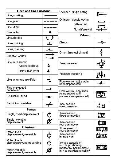
6-2. United States of American Standards Insti-
tute (USASI) Graphical Symbols. The USASI, the old American Standards Association
(ASA), and the Joint Industry Conference (JIC) are three systems of symbols used in circuit
diagrams. This manual uses the USASI symbols shown in Figure 6-2, pages 6-2 and 6-3.
Circuit Diagrams and Troubleshooting
6-1
FM 5-499
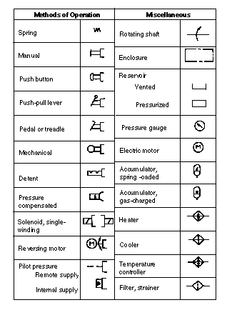
Figure 6-2. USASI graphical symbols
6-2
Circuit Diagrams and Troubleshooting
FM 5-499
Figure 6-2. USASI graphical symbols (continued)
Circuit Diagrams and Troubleshooting
6-3
FM 5-499
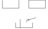
a. Reservoir. The symbol for a reser-
voir is a rectangle; the horizontal side is
the longest side (see Figure 6-3). If a res-
ervoir is vented to the atmosphere, the
top of the symbol is open. If a reservoir
Vented
Pressurized
reservoir
reservoir
is pressurized, the top is closed. Lines
that connect to a reservoir usually are
Line terminating
drawn from the top, regardless of where
above fluid level
they connect. If the line terminates
below the fluid level, it is drawn to the
bottom of the symbol. A line connected
Line terminating
to the bottom of a reservoir may be
below fluid level
drawn from the bottom of the symbol, if
the bottom connection is essential to the
Figure 6-3. Reservoir symbols
system's operation. For example, when
the pump's inlet must be charged or flooded by a positive head of oil above the inlet's port, they would be positioned above the pump symbol and the suction line drawn out the bottom
of the symbol. Every reservoir has at least two hydraulic lines connected to it; some have
more. The reservoir is usually the only component pictured more than once so that compo-
nents and return or drain lines to and from the reservoir are represented correctly.
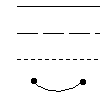
b. Lines. Figure 6-4 shows the symbols for hydraulic lines, which are as follows:
•
Working line: A solid line that represents a hydraulic pipe, tube, hose, or other
conductor that carries the liquid between components.
•
Pilot line: Long dashes that represent control lines.
•
Drain line: Short dashes that represent the drain lines for leaking oil.
•
Flexible line: A solid, arced line that is drawn between two dots which represents
a flexible line in the system.
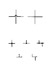
Figure 6-5, diagram A, shows crossed lines
that are not connected. Systems 1 and 2 repre-
Working line
sent two ways to indicate an intersection, one
with a loop, one without a loop. Diagram B
Pilot line
shows lines that are connected. The lines in
system 1 use a dot at the crossing, indicating
that loops are used to designate the crossing.
Drain line
The lines in system 2 do not use a dot at the
crossing, indicating that loops are not used at
Flexible line
the crossing.
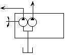
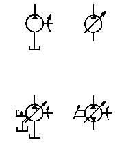
c. Pump. The basic symbol of a pump is a
Figure 6-4. Hydraulic line symbols
circle with a black triangle in the circle point-
ing outward (see Figure 6-6). The pressure line
from the pump is drawn from the tip of the triangle; the suction line is drawn opposite it.
The triangle indicates the flow direction. If a pump is reversible, it will have two triangles, one pointing out of each port. Port connections to the pump (or any other component except
the reservoir) are at the points where the lines touch the symbols. A variable (or adjustable) component is designated by an arrow drawn through the components at a 45-degree angle.
6-4
Circuit Diagrams and Troubleshooting
FM 5-499
d. Motor. Motor symbols are circles with
System 1
System 2
black triangles pointing inward, indicating that
to loop
not to loop
the motor receives pressure energy (see Figure
6-7, page 6-6). One triangle indicates a nonre-
versible motor; two triangles indicate a revers-
ible motor. Flow direction in a single triangle
is the way the triangle points. In the reversible
motor, studying the pump and valve symbols is
the way to trace the flow direction. The arrows
that are outside the lines show the flow direc-
Nonconnecting lines
tion, which is always away from the pump's
A
pressure port and into the motor port that is
connected to the pressure line. The opposite
port then discharges back to the tank.
System 1 to dot
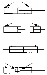
e. Cylinder. The basic cylinder symbol is a
simple rectangle (a barrel) and a T-shaped fig-
ure (a piston and a rod). The symbol can be
System 2 not to dot
drawn in any position. The following describes
four different cylinder symbols (see Figure 6-8,
page 6-6):
• Single-acting cylinder: One hydraulic
Connecting lines
line drawn to the basic cylinder symbol;
the end opposite the port is open.
B
• Double-acting cylinder: Both ends of
the symbol are closed; two lines meet
Figure 6-5. Crossing lines A and B
the basic cylinder symbol at the port
connections.
• Double-end rod cylinder: A rod line
extends from each end of the basic cylin-
der symbol.
• Cushioned cylinder: Small rectangles
are placed against the piston line. If the
Variable
cushion has an adjustable orifice, a
Fixed displacement
displacement
slanted arrow is drawn across the sym-
(simplified)
bol. There is no symbol for flow direc-
tion, so lines must be watched to see
where they are connected, which should
help determine flow.
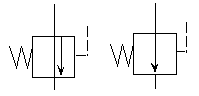
f. Pressure-Control Valves. The basic symbol
Reversible with
is a square with external port connections and
lever control
an arrow inside to show the flow direction (see
Figure 6-9, page 6-6). This valve operates by
Variable displacement
balancing the pump outlet to the reservoir.
pressure compensated
(complete)
Figure 6-6. Pump symbols
Circuit Diagrams and Troubleshooting
6-5
FM 5-499
Nonreversible
motor
Inlet
Inlet
Pilot
Valves
Spring
pressure
Outlet
Outlet
Valves
NORMALLY
NORMALLY
CLOSED
OPEN
Figure 6-9. Pressure-control-valve
symbols
Reversible
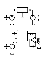
(1) Relief Valve (Figure 6-10). The relief
motor
valve's symbol goes between the pressure line and
the tank. The flow-direction arrow points away
from the pressure-line port and toward the tank
Figure 6-7. Motor symbols
port. When pressure in the system overcomes the
valve spring, flow is from the pressure port to the
tank port.
Ports
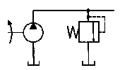
(2) Sequence Valve (Figure 6-11). A sequence
valve uses the relief valve. However, the inlet
port is connected to a primary cylinder line; the
outlet port is connected to the secondary cylinder
Double-acting
line. Pilot pressure from the primary cylinder
line sequences the flow to the outlet port when it
Port
Port
reaches the valve's setting. Since the sequence
valve is externally drained, a drain connection is
or
added to the symbol at the drain's location in the
Single-acting
valve.
(3) Check Valve (Figure 6-12, page 6-8). A
check valve uses a sequence valve for free return
flow when the cylinders are reversed. In Figure
Double end rod
6-12, diagram A shows the valves as separate
units. Diagram B shows the check valve built into
Nonadjustable
Adjustable
the sequence valve. The box around the valves is
an enclosure, which shows the limits of a compo-
nent or an assembly that contains more than one
component. The enclosure is an alternate long
and short dashed line. External ports are
Cushioned
assumed to be on the enclosure line and indicate
connections to the components.
Figure 6-8. Cylinder symbols
6-6
Circuit Diagrams and Troubleshooting