•
Perform repairs, taking time to do the job well.
a. Causes of Improper Operations. If improper operation does occur, the cause can generally be traced to one of the following:
•
Use of the wrong oil viscosity or type.
•
Insufficient fluid in the system.
•
Presence of air in the system.
•
Mechanical damage or structural failure.
•
Internal or external leakage.
•
Dirt, decomposed packing, water, sludge, rust, and other foreign matter in the
system.
•
Improper adjustments.
•
Heat exchanger that is plugged, dirty, or leaking.
b. Testing a Hydraulic Circuit. To test complete or individual parts of a hydraulic circuit, use a hydraulic circuit tester (see para-
graph 2-8, page 2-18). The best tester to use is
a compact portable unit that can check flow,
pressure, and temperature.
c. Comparing Test Results with Specifica-
Steering column
tions. Hydraulic-powered systems are power-
transmission systems. The only purpose of the
components and the circuit is the controlled
transfer of power from the motor shaft to the
point of effective work.
fp
HP = --------
1, 714
Steering valve
Steering gear
where—
HP = hydraulic horsepower
f = flow, in GPM
Figure 6-24. Semi-integral power-
p = pressure, in psi
steering system
Circuit Diagrams and Troubleshooting
6-13
FM 5-499
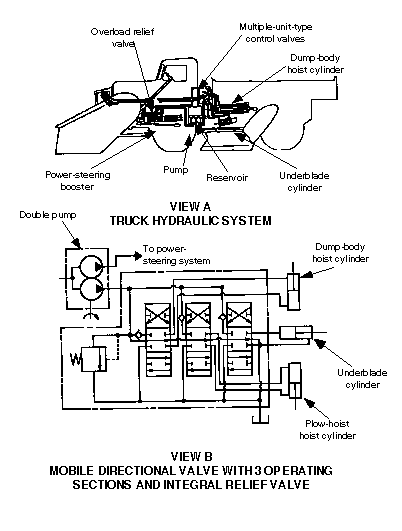
Figure 6-25. Hydraulic circuit diagram for a road-patrol truck
6-14
Circuit Diagrams and Troubleshooting
FM 5-499
By measuring those two factors at the same time, it is possible to read the effective out-
put at any point. Comparing test results with specifications will give the necessary fault-
finding facts.
d. Slippage. All hydraulic systems have some slippage (see paragraph 3-4, page, page 3-3) even when new. As wear increases, slippage at wear points increases, causing a
decrease in GPM. However, system pressure is maintained. In time, wear can be so great
that all flow is lost. Only at a complete breakdown will a pressure gauge show where the
trouble is. Conducting a flow, pressure, and temperature (FPT) test would have indicated
such a problem and avoided a complete breakdown.
NOTE: At low oil temperature and low pressure (or light loads) the
machine will continue to operate but at less speed.
e. Flow and Pressure. Always test flow and pressure together. Connect a hydraulic
tester into the hydraulic circuit at various points to isolate and check components (pumps,
valves, or cylinders) for efficiency. Figure 6-26 shows a hydraulic tester, connected to the pump's output, checking the flow at various pressures that, in turn, checks the pump's performance against the recommended specification. When isolating and testing individual
components with a hydraulic tester, direct the return fluid to the reservoir. If the fluid
returns to the reservoir through the system's piping, you will not get a correct reading
because of buildup of back pressure.
Test the
whole circuit as
TROUBLESHOOTING A HYDRAULIC SYSTEM
described, and
then isolate por-
tions and test
Isolate and check the following:
for a complete
analysis of the
• Directional-control valves
system. If a test
for leakage, efficiency.
on a full circuit
• System’s relief valves
indicates a mal-
for leakage, proper settings.
function, isolate
• Pump’s GPM flow at
a portion and
various pressures.
test the remain-
• Cylinder’s efficiency.
ing portions
until you find
the malfunction-
ing part. Gener-
ally, cylinders
Figure 6-26. Hydraulic tester connected to a pump’s output
will fail first.
Packing will
wear because of friction and loading against the cylinder walls. Therefore, isolate the cylinders first. If test results indicate that the circuit is operating properly, the cylinders have a problem. During testing, determine the setting and condition of the relief valve. If further tests are necessary, isolate the directional-control valve to check the pump's efficiency and inlet hose.
f. Other Conditions. Other problems could occur that are not directly related to nor caused by the various parts of the hydraulic system. These problems could show the same
Circuit Diagrams and Troubleshooting
6-15
FM 5-499
general malfunctions of an improperly operating system. Examples are leaking hose, pack-
ing glands, and seals, which would be visually evident; a bind in the directional-control
valve or the cylinder's piston rod; a dented or deformed hydraulic cylinder; or a crimped or
restricted pressure line, which would be harder to detect.
g. Specific Troubles, Causes, and Solutions. Tables 6-1 through 6-5, pages 6-17 through 6-21 list some possible problems and solutions in a hydraulic system.
6-16
Circuit Diagrams and Troubleshooting
FM 5-499
Table 6-1. Problems and solutions with pump operations
No Fuel Delivery
Problems
Solutions
Fluid level in the reservoir is low.
Add the recommended oil; check the level on both sides of
the tank's baffle to be certain that the pump suction is sub-
merged.
Oil intake pipe or inlet filter is plugged.
Clean the filter; otherwise, remove the obstruction.
Air leak in the inlet line prevents priming or causes
Repair the leaks.
noise and irregular action of the control circuit.
The pump shaft turns too slowly to prime itself
Check the appropriate manual's minimum speed recommen-
(vane-type pumps only).
dations.
The oil viscosity is too heavy to pick up the prime.
Use a lighter oil viscosity; follow the appropriate manual's
recommended temperatures and services.
Shaft rotates in the wrong direction.
Reverse the rotation immediately to prevent seizure and
parts from breaking due to lack of oil.
Pump shaft is broken, parts are broken inside the
See the appropriate manual for replacement instructions.
pump, or the shear pin or shear linkage is broken.
Pump has dirt in it.
Dismantle and clean the pump; flush the system.
The stroke is incorrect on variable delivery pumps.
See the appropriate manual for instructions.
No Pressure in the System
Pump does not deliver oil for any reasons given in
Follow the remedies given.
above section.
• Relief-valve setting is not high enough.
• Increase the pressure setting of the valve; check the
appropriate manual for the correct pressure.
• Relief valve leaks.
• Check the seat for score marks and reseat.
• Relief-valve spring is broken.
• Replace the spring and readjust the valve.
Vane is stuck in the rotor slots (vane-type pumps
Inspect for wedged chips; inspect the oil for excessive vis-
only).
cosity.
The head is loose (very infrequent occurrence).
Tighten the head; check the appropriate manuals before
tightening.
Oil to the tank recirculates freely through the sys-
Check to see if a return line is open due to either a direc-
tem.
tional valve set in the open-center neutral position or some
other valve is left open.
Control valves have internal leakage.
Block off various parts of the circuit to determine where the
leak is; repair when located.
Noisy Pump
Intake line, filter, or restricted intake pipe is partially
Clean out the intake or strainer, or eliminate the restrictions;
clogged.
ensure that the inlet line is open.
Circuit Diagrams and Troubleshooting
6-17
FM 5-499
Table 6-1. Problems and solutions with pump operations (continued)
Noisy Pump (continued)
Problems
Solutions
• Air leaks occur at the pump's intake piping joints.
• Pour oil on the joints while listening for a change in the
operating sounds; tighten the joints as required.
• Air leaks are present at the pump's shaft packing.
• Pour oil around the shaft while listening for a change in
the operating sounds; follow the appropriate manual
instructions when changing the packing.
• Air is drawn in through the inlet pipe openings.
• Ensure that the inlet and return lines are well below the oil
level in the reservoir; add oil to the reservoir if necessary.
Air bubbles are present in the intake oil.
Use hydraulic oil that has a foam depressant.
Reservoir's air vent is plugged.
Clean or replace the breather.
Pump is running too fast.
See the appropriate manuals for recommended maximum
speeds.
Oil viscosity is too high.
Use a lower oil viscosity; check the appropriate manuals for
the recommended temperatures and services.
Coupling is misaligned.
Realign the coupling.
Pump vane is stuck (vane-type pump).
Inspect the pump for wedged chips or sticky oil; reassemble.
Parts are worn or broken.
Replace worn or broken parts.
External Oil Leaks
Shaft packing is worn.
Replace the worn parts.
A head of oil is present on an inlet-pipe connection.
Keep all the joints tight; slight leakage may be necessary.
Excessive Wear
Abrasive matter in the hydraulic oil is being circu-
Install an adequate filter or replace the oil more often.
lated through the pump.
Oil viscosity is too low for working conditions.
Check the appropriate manual's recommendations or the
lubrication chart for information.
Sustained high pressure occurs above the maxi-
Check the relief or regular valve's maximum setting.
mum pump rating.
Drive is misaligned or belt drive is tight.
Check the parts; correct the problem.
Air recirculation is causing a chatter in the system.
Remove the air from the system.
Broken Parts Inside the Pump Housing
Excessive pressure above the maximum pump rat-
Check the relief or regulator valve's maximum setting.
ing is present.
Seizure occurs due to lack of oil.
Check the reservoir level, oil filter, and possibility of restric-
tion in the inlet line.
Solid matter is being wedged in the pump.
Install a filter in the suction line.
Head screws are too tight.
Check appropriate manual’s recommendations; adjust.
6-18
Circuit Diagrams and Troubleshooting
FM 5-499
Table 6-2. Problems and solutions with actuating mechanism
Inoperative System
Problems
Solutions
System fails because of any problem listed in
Follow recommened solution.
Tables 6-1 through 6-5.
Mechanism Creeps (Stopped in Intermediate Position)
Internal leakage occurs in the actuating cylinders or
Replace the piston packing or cylinder, if the walls are
operating valves.
scored; replace or repair the valve.
Longer Operating Times Than Specified
Air is present in the system.
Bleed the system.
Actuating cylinder or directional-control valve has
Replace the piston packing or replace the cylinder if the
an internal leak.
walls are scored; replace or repair the valve; clean the unit to
remove foreign matter; check the cam clearance.
Pump is worn.
Repair or replace the pump.
Action is sluggish on start up but less so after oper-
Check appropriate manual’s lubrication order.
ating temperatures have increased, or action slows
down after warm up. Depending on equipment and
circuit design, could indicate that the oil viscosity is
too high.
External Oil Leaks
End caps leak.
Tighten caps, if possible, or replace the gasket.
Chevron seals leak.
Adjust or replace the seals.
Abnormal Packing-Gland Wear
Cylinder is not securely fastened to the frame,
Tighten the cylinder; check it periodically.
causing it to vibrate.
Cylinder and piston-rod extension are misaligned.
Check the parts; correct the problem.
Side load occurs on the piston rod.
Check for cylinder alignment or worn pins or ball joints.
Circuit Diagrams and Troubleshooting
6-19
FM 5-499
Table 6-3. Problems and solutions with heating oil
Heating Caused by Power Unit (Reservoir, Pump, Relief Valve, Coolers)
Problems
Solutions
Relief valve is set at a higher pressure than neces-
Check manual for the correct pressure; reset the relief valve.
sary; excess oil dissipated through increased slip-
page in various parts or through the relief valve or
directional valve.
Internal oil leaks occur due to wear in the pump.
Repair or replace the pump.
Oil viscosity is too high.
Check appropriate manual for correct oil viscosity to use at
various temperatures.
Overhauled pumps may be assembled too tightly,
Follow the appropriate manuals when rebuilding a pump.
which reduces clearances and increases friction.
Pump has leaking check or relief valves.
Repair or replace the valves.
Oil cooler or coolant functions improperly in cut off.
Inspect cooler; clean inside and outside; ensure that air flow
or coolant flow around fins is not cut off.
Conditions in System Cause Excessive Heating
Lines are restricted.
Replace the lines if they are crimped; remove any obstruc-
tion if lines are partially plugged.
Large pump deliveries do not unload properly.
Ensure that the open-center valves are neutralized and that
any pressure-relieving valves are in the correct position.
(Allow only small pumps to stay at high pressures when run-
ning idle for long periods.)
Radiation is insufficient.
Use artificial cooling.
Pump has internal leaks.
Locate leaks; replace the packing.
Reservoir is too small to provide adequate cooling.
Replace unit with a larger reservoir.
Valves or piping is undersized.
Check flow velocity through the lines and valves; compare
them with the manual’s recommendations. If velocity is
excessive, install larger equipment.
6-20
Circuit Diagrams and Troubleshooting
FM 5-499
Table 6-4. Problems and solutions with fluid motors
Motor Turns in the Wrong Direction
Problems
Solutions
Conductors are crossed between the control valve
Check circuit to determine the correct conductor connection
and the motor.
between the control valve and motor.
Motor Does Not Turn or Does Not Develop Proper Speed or Torque
System’s overload-relief-valve adjustment is not set
Check system’s pressure; reset the relief valve.
high enough.
Relief valve sticks open.
Clean or replace the relief valve; adjust.
Oil to the reservoir freely recirculates through the
Check control-valve linkage; directional-control valve may be
system.
in open-center neutral.
Driven mechanism binds because of misalignment.
Check the motor shaft for alignment.
Pump does not deliver enough GPM or pressure.
Check pump’s GPM and pressure; repair or replace.
Motor yoke is not set at the proper angle.
Adjust the pump’s yoke angle.
External Oil Leak From the Motor
Seals leak (drain may not be connected from motor
Check motor for 3rd line (a drain line that must go to tank
to tank).
used on piston and vane motors).
NOTE: See Table 6-1 for improper operation of pump.
Table 6-5. Problems and solutions with accumulator operation
Sudden Drop in Accumulator Pressure (Position of Selector Valve is Changed)
Problems
Solutions
Accumulator has an internal or external leak.
Repair the leak or replace the accumulator.
No Pressure When Pump Stops Running (Normal Pressure When Pump Was Running)
Hydraulic line has a leaking gas or check valve.
Replace the check or the gas valve.
Sluggish Response for Accumulator
Oil screen in the accumulator stops.
Dismantle the accumulator; clean the screen.
Gas precharge is not sufficient.
Precharge according to recommendations in the manual;
check for gas leaks.
NOTE: Release all internal pressure before making repairs on accumulators.
Circuit Diagrams and Troubleshooting
6-21
FM 5-499
CHAPTER 7
Electrical Devices:
Troubleshooting and Safety
This chapter describes the process of locating the cause of malfunctions in electrical circuits associated with hydraulic-control systems. The information includes testing devices and types of grounding points. Also addressed in this chapter are the safety measures personnel should take when working on or around electrical circuits.
7-1. Hydraulics and Electricity. Hydraulics and electricity are often compared because the systems have similarities. A hydraulic circuit requires a power source (usually a pump), a load device (actuator), and conductors. The circuits differ mainly in the—
• Types of devices used to control, direct, and regulate the hydraulic fluid flow.
• Type and capacity of the actuators used to accomplish the work, which varies,
depending on the application.
An electrical circuit also requires a power source (battery, generator), a load device
(light, bell, motor), and proper connections. An assortment of devices also controls, directs, and regulates the flow of electrical current.
Hydraulic and electrical components are usually represented on diagrams by their own
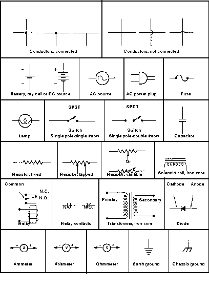
set of standardized symbols. Electrical diagrams are often called schematics. Figure 7-1,
page 7-2, shows some of the more common symbols. Hydraulic and electrical systems and
circuits have many differences. For example, electrical current is invisible, hydraulic fluid is not; electrical current flows through solid wires, hydraulic fluid flows through hollow lines.
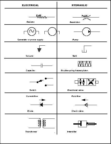
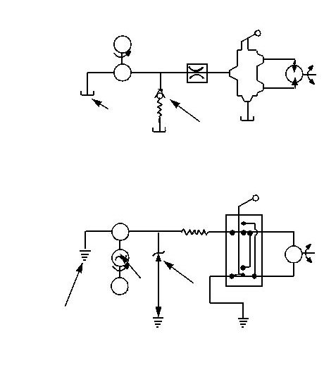
Figure 7-2, page 7-3, shows symbols for electrical and hydraulic components. Figure 7-3,
page 7-4, compares a hydraulic circuit and an electrical circuit.
7-2. Troubleshooting Electrical Devices. Electrical troubleshooting is the process of locating the cause of malfunctions in electrical circuits. The following paragraphs contain
some general troubleshooting information as well as specific tests for determining the status of some electrical devices. Skill in troubleshooting electrical equipment and circuits
requires—
• Knowledge of electrical principles to understand how a circuit or device should func-
tion.
• Skill in reading and interpreting electrical schematics, diagrams, product data, and
so forth.
• Skill in operating test equipment and interpreting test measurements.
• Ability to analyze problems in a logical manner.
Following systematic steps that narrow down the problem to a smaller area of the
equipment is much more efficient than trial-and-error methods. The troubleshooting
Electrical Devices: Troubleshooting and Safety
7-1
FM 5-499
Figure 7-1. Common electrical schematic symbols
7-2
Electrical Devices: Troubleshooting and Safety
FM 5-499
Figure 7-2. Comparison of electrical and hydraulic components
Electrical Devices: Troubleshooting and Safety
7-3
FM 5-499
Directional valve
Power source
M
Motor
Load
(motor)
Pressure drop
Pump
(Restriction
orifice)
Pressure reference
(tank)
Regulation
(relief valve)
HYDRAULIC CIRCUIT
Directional switch
Power source
Power supply
Voltage drop
(Resistor)
Generator
Load
(motor)
Motor
M
Regulation
(zener diode)
Voltage reference
(ground)
ELECTRICAL CIRCUIT
Figure 7-3. Comparison of electrical and hydraulic circuits
7-4
Electrical Devices: Troubleshooting and Safety
FM 5-499
procedure detailed below can be very useful in organizing the problem-solving effort and
reducing equipment downtime:
a. Procedure.