2
3
4
5
6
7
Time in s
Fig. 13c. Results – min torque priority
256
New Approaches in Automation and Robotics
By changing the weighting factors it is also possible to shift the focus more towards other
attributes. For instance one can achieve a reduction of the waste gas emission by a setpoint
for corresponding λ=1 and increasing the weighting factors of the lambda path.
The results are shown in figure 13c for the same setpoint and load steps as in the example
above. It is visible that the torque adjustment is (compared to figure 13a) slower and the
controller output for the fuel path is used only marginally.
6
5
4
m
3
rque in N
Torque setpoint
To 2
Torque
1
0
2.1
2.2
2.3
2.4
2.5
2.6
2.7
2.8
2.9
3
Time in s
30
20
m
Torque (fresh air)
Torque (exhaust gas)
10
Torque (ignition angle)
rque in N
Torque (lambda)
To
0
-10
2.1
2.2
2.3
2.4
2.5
2.6
2.7
2.8
2.9
3
Time in s
Fig. 13d. Results – min torque priority
As mentioned in section 2 the described control approach allows to switch smoothly
between torque, speed or acceleration control. This can be simply achieved by the model
extension (described in section 2, equation 3) and appropriate weighting parameters for the
MPC. Only by shifting the weighting factors one can switch from speed control to torque
control and back.
The plots in figure 14 demonstrate how this control mode works. In this example we used
only the fresh air and the ignition path for torque control. Up to 3 seconds the controller
should work as a speed controller. From then it should work as a torque controller. At
approximately 6 seconds the weighting factors where switched back to speed control mode
values. Equation 21 represents the linear model which is used internally by the MPC for this
example.
⎛
Torque
Engine
⎞ ⎛ G ( s) G ( s)
11
12
⎞
⎜
⎟
⎜
⎟ ⎛ Torque
Setpoint
Air
Fresh
⎞
⎜
Speed
Engine
⎟ = ⎜ G ( s) G ( s)
(21)
21
22
⎟ ⋅⎜⎜
⎟⎟
⎜
⎟ ⎜
⎟ ⎝Δ TorqueI
⎠
⎝Δ
Setpoint
Angle
gnition
Torque
0
G ( s)
Angle
Ignition
⎠ ⎝
32
⎠
Advanced Torque Control
257
Switching between speed and torque control can simply be realized by changing some
weighting factors. The behaviour of the MPC changes automatically. This is a very
convenient way to change for instance to the idle speed control mode and back to torque
control.
In figure 14 first the speed control is active. The speed follows the desired characteristic
whereas the torque is different from the corresponding setpoint. After changing the
weighting factors the torque will be adjusted to the setpoint and the engine speed is only
marginally considered by the controller.
Time period in
Active
Torque weighting
Speed weighting
s
Control
factor
factor
0 … 2.5
Speed control
0
1
Torque
2.5 …6
1 0
control
6 … 8.5
Speed control
0
1
Table 1. Enabled control
m 1100
p
r 1000
Speed Setpoint
in
900
Speed
eed
800
p
0
1
2
3
4
5
6
7
8
S
Time in s
m N
20
in -2
-4
Torque Setpoint
-6
que
Torque
-8 0
1
2
3
4
5
6
7
8
Tor
Time in s
m 30
N
Torque about Fresh Air
20
in
Torque about Ignition Angle
10
que
0 0
1
2
3
4
5
6
7
8
Tor
Time in s
m 6
N
4
Load Torque
in 2
que 0 0
1
2
3
4
5
6
7
8
Tor
Time in s
Fig. 14. Speed and Torque Control
258
New Approaches in Automation and Robotics
At approximately 6 seconds the engine speed control mode was activated again. The speed
should decrease here from the current value smoothly along a given trajectory. It is visible
in figure 14 that the controller solves the differing control tasks properly. In the third plot
(from the top) one can see also that the ignition path control variable is used transient by the
controller. Stationary the setpoint is adjusted.
5. Conclusion
In the chapter we discussed a control approach for torque control of gasoline engines.
Because of several actuating variables and control requirements the process to be controlled
is multivariable. The actuating variables are usually bounded and the effects on the engine
torque are nonlinear. Hence direct use of the actuator variables for torque control generally
produces plenty of problems.
The two layer approach described in the chapter allows the application of standard control
methods. The main idea of the control structure is to compensate or alleviate the
nonlinearity behaviour by subordinate control circuits. All the physical actuating variables
are substituted by setpoints of the subordinate systems. The torque controller so can be
designed on base of linear models. Additionally only bounds of some control variables have
to be considered.
An appropriate standard control concept for the superordinate torque controller is the
model predictive control principle. For the implementation we used a state space approach.
The optimization problem is solved by the active set algorithm. For lower computation
effort a solution with constant parameters was introduced. But this solution doesn't consider
constraints and loss performance can occur.
The three examples in section 4 show the capability of the control concept. The extension of
the control structure is possible simply by completing the model and appropriate weighting
parameters. In this way the controller should be able to handle more actuating variables or
other requirements.
The control quality depends on the quality of the model. Although the subordinate control
circuits contribute to the linearization of the process behaviour the dynamic parameters may
be dependent on engine speed or load. For that case a set of linear models could be useful.
The control approach described in this chapter demonstrates that modern control
approaches have considerable potential to improve the performance of embedded control
systems. In addition to better performance also the variability of the systems and the ability
to handle different control requirements could improve.
6. References
Auckenthaler, T.S. (2005). Modelling and Control of Three-Way Catalytic Converters,
Institute of Technology, Zürich, Dissertation
Back, M. (2005). Prädiktive Antriebsregelung zum energieoptimalen Betrieb von
Hybridfahrzeugen, Institut für Regeluns- und Steuerungssysteme Universität
Karlsruhe, Dissertation
Bauer, H. (2003): Ottomotor-Management: Systeme und Komponenten, Friedr. Vieweg &
Sohn Verlagsgesellschaft mbH
Advanced Torque Control
259
Brand, D. (2005). Control-Oriented Modeling of NO Emissions of SI Engines, Institute of
Technology, Zürich, Dissertation
Basshuysen, R. van; Schäfer, F. (2002): Handbuch Verbrennungsmotor – Grundlagen,
Komponenten, Systeme und Perspektiven, Vieweg und Sohn Verlagsgesellschaft
mbH, Braunschweig/Wiesbaden
Dittmar, R.; Pfeiffer, B. (2004). Modellbasierte prädiktive Regelung, Oldenbourg Verlag
München, Wien
Dünow, H.-P. (2004). Anwendung Modellprädiktiver Regelungen, Forschungsbericht,
Hochschule Wismar, Fachhochschule für Technik, Wirtschaft und Gestaltung –
Fachbereich Elektrotechnik und Informatik
Dünow, H.-P.; Lekhadia, K.N.; Köller, M.; Jeinsch, T. (2005). Model based predictive control
of spark ignition engine, Proceedings of MMAR
Fletscher, R.R (1987). Practical Methods of Optimization, Wiley, 2nd edition
Fritzsche, C.; Dünow, H.-P.; Lampe, B.; Schultalbers, M. (2007). Torque Coordination of
Spark Ignition Engines based on Predictive Control, Proceedings of MMAR,
Szczecin, Poland
Gill, P.E.; Murray, W.; Wright, M.H. (1991). Numerical Linear Algebra and Optimization,
Volume 1, Addison Wesley
Grimble, M.J. (2001). Industrial Control Systems Design, John Willey & Sons, LDT
Chichester, New York, Weinheim, Brisbane, Singapore and Toronto
Grohe, Heinz (1990). Otto- und Dieselmotoren, Vogel Fachbuchverlag, Auflage 9,
Würzburg, Germany
Guzella, L. and Onder, C.H. (2004). Introduction to Modeling and Control of Internal
Combustion Engine Systems, Springer Verlag Berlin, Heidelberg, Germany
Johansen, T.A. (1994). Operating Regime based Process Modelling and Identification, PhD
Thesis, Department of Engineering Cybernetics – The Norwegian Institute of
Technology – University of Trondheim
Johansen, T.A.; Murray-Smith, R. (1997). Multiple Model Approaches to Modelling and
Control, Taylor & Francis London
Kristoffersson, I. (2006). Model Predictive Control of a Turbocharged Engine, School of
Electrical Engineering and Information Technology, Stockholm
Lekhadia, K.N.; Dünow, H.-P.; Jeinsch, T. (2004). Active Set Method Approach for Real Time
Model Predictive Engine Control, In: Modellierung, Regelung und Diagnose von
Verbrennungsmotorprozessen, 2. ASIM Workshop Wismar
Lekhadia, K.N. (2004a). Development of OP Algorithms for Real-Time Predictive Control
Systems, Master Thesis, FH Darmstadt
Maciejowski, J.M. (2002). Predictive Control with constraints, Prentice Hall
Pulkrabek, Willard (2004). Engineering Fundamentals of the Internal Combustion Engine,
Prentice Hall
Rückert, J.; Richert, F.; Schlosser, A.; Abel, D.; Herrmann, O.; Pfeifer, A.; Pischinger, S.
(2003). Konzepte zur Regelung von Ladedruck und AGR-Rate beim Nutzfahrzeug-
Dieselmotor, GMA-Kongress – VDI-Berichte 1756, VDI-Verlag Düsseldorf
260
New Approaches in Automation and Robotics
Salgado, M.E.; Godwin, G.C.; Greabe, S.F. (2001). Control System Design, Prentice Hall
London
Urlaub, Alfred (1995). Verbrennungsmotoren – Grundlagen, Verfahrenstheorie,
Konstruktion, Springer Verlag Berlin, Heidelberg, Germany
15
Design, Simulation and Development of
Software Modules for the Control of Concrete
Elements Production Plant
Georgia Garani and George K. Adam
Technological Educational Institute of Larissa
Dept. of Informatics and Telecommunications
41110 Larissa
Greece
1. Introduction
Manufacturing and control procedures for automation require many different technologies.
The last decade has seen computer technology applied widely in industrial production,
particularly in manufacturing processes not generally associated with high technology. The
technology used in the automated production of moulded concrete elements for the
architectural and building industry has changed dramatically in recent years. The
introduction of Computer Integrated Manufacturing (CIM) between 1960 and 1980 (Trybula
& Goodman, 1989), e.g., numerically controlled machines, followed in the 1980 to 1990
developments in robotics, e.g., advanced robotics (Shell & Hall, 2000) had a significant
impact on automating the production of moulded concrete elements.
The types of system that produce concrete elements are mainly machines using hydraulic
compression and extraction. This is the most common method used to form the complex
product shapes required by the architectural and building industry. These machines can be
either stationary, or they can be mobile, with automated mobile machines being the machine
of preference these days. Other relevant ancillary equipment used in the automated
production of concrete elements are aggregate mixers, material storage silos and conveyors.
The concrete elements required by architects and builders often include complex geometric
shapes; it is for this reason that the central process in their production is the hydraulic press.
Complex geometric shapes in concrete and their quality control can only produced using
automated compression machinery (Isayev, 1987; Reinhart, 1987). The various phases of this
process are (1) material mixture; aggregates of variable form tightly compressed into a
mould and (2) compression to form and extract the desired product.
The application of computer aided systems to hydraulic press machines has increased the
range and variety of concrete elements that these machines can produce for the architectural
and building industry (e.g., ZENITH, KNAUER, BESSER, etc.). The consistency and quality
control of landscape and architectural products, such as concrete blocks, curb stones,
palisades, paving stones, etc., has improved through introducing computer aided systems.
Computer-control systems, teleoperation and automation technology, modelling and
simulation tools are some of the technologies and techniques used to acquire the desired
262
New Approaches in Automation and Robotics
functionality in operation control and quality in production (Chryssolouris, 1992; Gutta &
Sinha, 1996; Marvel & Bloemer, 2000).
However, quite often various problems arise during the attempt of systems modelling and
control, in most cases due to insufficient structuring of the system in the real world. In these
cases, usually artificial intelligence techniques are being applied (Fishwick & Luker, 1991;
Hwang et. al., 1995). For this reason, the design and control of automated production system
requires an effective development system that enables the design specifications to be
implemented and tested prior to the actual implementation and control of the production
system. The generation and implementation of such systems has become essential to the
development of automated production systems (Rao et al., 1993; Nise, 1995; Shetty & Kolk,
1997; Srovnal & Pavliska, 2002).
Qualitative modelling approaches have been applied for a long period of time with quite
successful results in most of the cases (Forbus, 1984; Groumpos & Krauth, 1997; de Kleer &
Brown, 1984; Trave-Massuyes, 1992; Garani & Adam, 2007). One of the aims of this research
was to accomplish an adequate control structure for a synchronised co-operation of the
plant machines. Previous work on applications of qualitative modelling techniques (Adiga
& Gadre, 1990; Lamperti & Zanella, 2003; Mak et. al., 1999; Zhang et. al., 1990) shows that
there is still further need of work to be carried out for the development of highly intelligent
qualitative modelling approaches.
This chapter presents the application of design, simulation and software development
techniques for the operation and control of a concrete elements production plant and
particularly, an automated mobile press machine (RoboPress). Teleoperation is required in
operating the mobile press machine for performing the actual production procedures. The
plant is consisted of various machines such as a press machine for concrete elements
production, a mixing machine for aggregates mixing, aggregates storage silos, transport
buckets and conveyors, etc. The design, operation and control of a concrete mixer machine
and an autonomous mobile hydraulic press machine are discussed in detail. The whole
system automates the production of moulded concrete elements for architectural and
building projects. The research work demonstrates how the design of a state-of-the-art
industrial plant can be optimised by using qualitative modelling and simulation from
artificial intelligence and other engineering software tools. Further on, it shows how an
efficient control algorithm for operating the group of machines can be derived from a
qualitative modelling approach.
The rest of this chapter is structured as follows: the following section describes the
application environment of this research; in section 3 a detailed description of the overall
plant control system is provided; section 4 provides details of the modelling and simulation
techniques used for the development and verification of the overall system’s operation and
control algorithm prior to its implementation; in section 5 details are given for the system
performance evaluation and implementation procedures of the software control modules
and algorithms. The chapter is concluded in section 6, which presents the outcomes and
future research work.
2. Application environment
The concrete plant under investigation and control is consisted of a group of machines
including a mobile press machine for the concrete elements production, an aggregates’
mixing machine, aggregates’ storage silos, a forklift loader, feeding conveyors, etc. Other
Design, Simulation and Development of Software Modules for the Control of
Concrete Elements Production Plant
263
basic machine components include the electronic control board based on a Hitachi EC series
programmable logic controller of type EC-60HRP. That unit offers up to 60 I/O points,
direct PC connection (RS232) and monitoring. A number of solid state inductive proximity
sensors of Telemecanique type XS7C40NC440 for industrial applications and PLC
compatible are employed, in perfect compatibility with the electronic automated system for
presence detection. The overall control is based on a closed-loop control system, with the
PLC unit to control real-time processes, under the operator’s control. The driving force
behind the above control system is the control software, the creation of which is based on
the construction and execution of descriptive qualitative models.
The concrete elements production of the plant varies from 6000 blocks per day (8hours) up
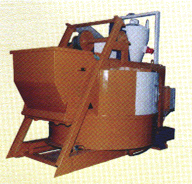
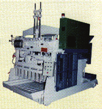
to 14000. Two of the main machines of interest, press and mixer machine, are shown in Fig.
1 while an overall configuration of the concrete plant is shown schematically in Fig. 2.
Fig. 1. Press and mixer machines
cement silo mixer
press
machine
machine
forklift
aggregates silos
concrete elements
mixer loader
conveyor
Fig. 2. Concrete plant configuration
The press and mixer machines are constructed mainly of mechanical and electrical parts and
devices, incorporating electrical boards, PLC units and other electronic equipment.
Basically, the plant operates as follows: aggregates from the storage silos are being supplied
through a feeding conveyor into the mixer machine and the wet concrete produced is
transported by a forklift loader into the press machine for the actual production of the
concrete elements. A simplified functional diagram of plant’s overall operation cycle is
shown in Fig. 3.

264
New Approaches in Automation and Robotics
press
concrete
blocks
out
forklift
loader
aggregates silos
in
mixer
Fig. 3. Plant’s operation cycle
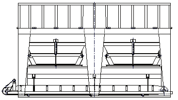
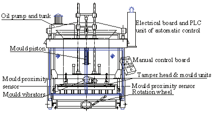
2.1 The mobile press machine
The press machine is one of the most important production units of the concrete plant (Fig.
4). The machine produces a variety of concrete products such as blocks, curbs, paving
stones, etc. It is consisted mainly of mechanical and electrical parts and devices, the
electrical board and the electronic control system based on a PLC unit (Hitachi EC series)
and other electronic equipment. The machine is mobile, based on a four wheels metallic
base. Other basi