The steering wheel of your dreams
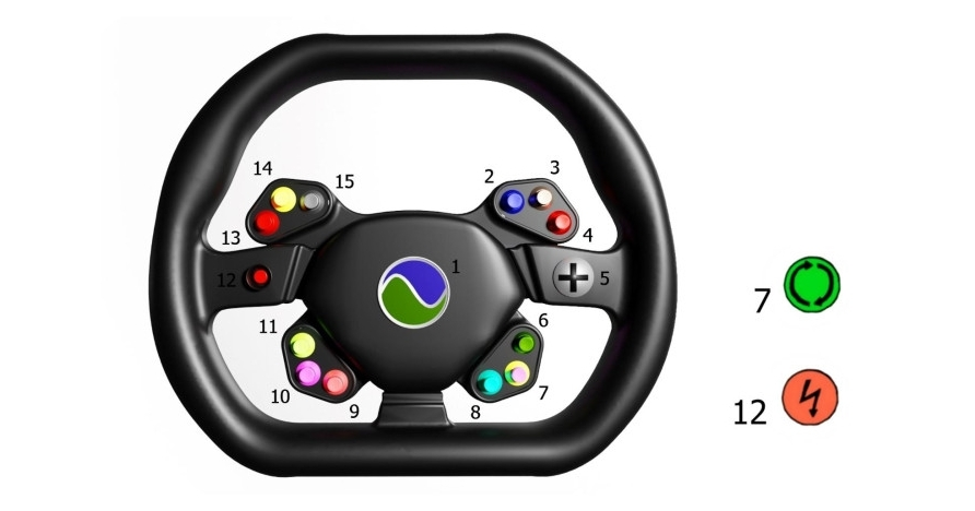
1 — sound signal; 2 — glass washer; 3 — wipers; 4 — right turn signal; 5 — pad menu; 6 — reverse; 7 — movement around the axis; 8 — voice assistant; 9 — alarm; 10 — speed limiter; 11 — driving mode; 12 — hyper speed; 13 — left turn signal; 14 — low beam, high beam; 15 — blowing glass.
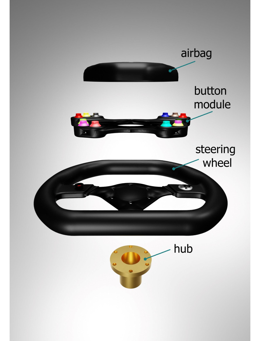
The steering wheel of the DUBINA EVO is designed for sporty driving. Steering wheel diameter 310 mm. The small diameter of the steering wheel increases the steering speed. The steering wheel is made of carbon fiber. Carbon has great strength, low weight and low thermal conductivity. The steering wheel consists of four parts: an airbag, a module with buttons, a steering wheel, a steering wheel hub. The button module is attached to the steering wheel. A printed circuit board with shift registers and control buttons is installed inside the module. The peculiarity of the steering is that there is no steering shaft. Instead, a magnetic sensor is used. A magnetic sensor installed in a fixed part of the dashboard housing determines the position of the steering wheel with an accuracy of 0.06 degrees. The advantage of using a magnetic sensor is small size, contactless operation, high accuracy, long working life.
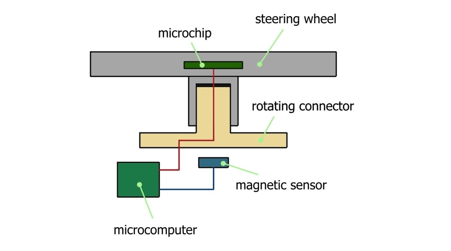
Steering wheel connection diagram.
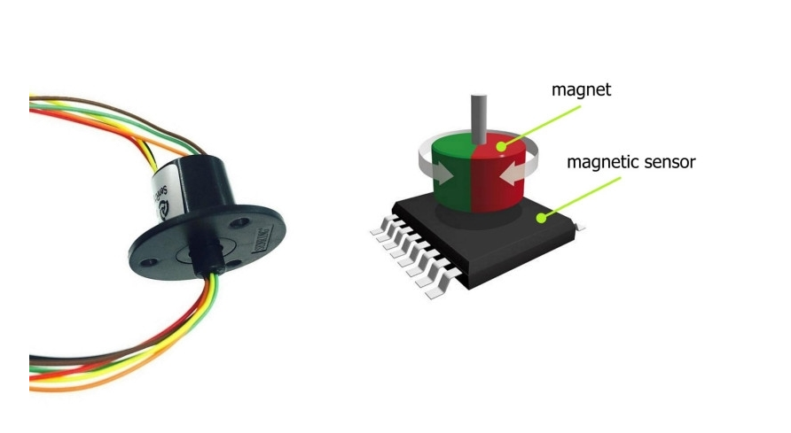
Rotating connector and magnetic pickup.
The signals from the buttons on the steering wheel are transmitted through the 74HC165 shift registers mounted on the printed circuit board in the steering wheel. Vehicle computer receives serial digital signals from 74HC165 shift registers
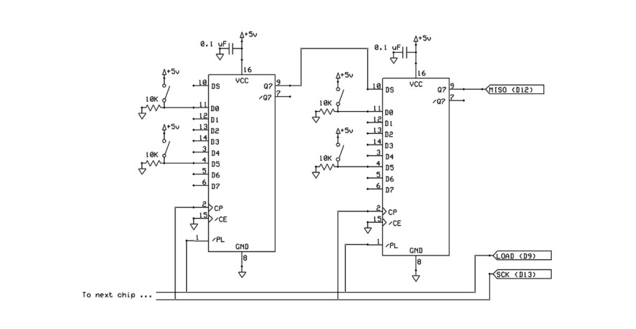
Diagram of connecting the steering wheel buttons to the shift registers.
The 74HC165 is a shift register that converts a parallel input to a serial output. It allows you to increase the number of digital inputs of the microcontroller. The chip converts the input parallel signal on 8 pins (Dx) to the output serial signal on 1 pin (Q7). The transmission is synchronous. An additional pin (CP) is used for the clock. Also, a separate pin controls the data register (PL), which allows you to “load” a parallel signal for sequential reading from 8 outputs at a time. Thus, from the three pins of the microcontroller, you can get 8 digital inputs. From the 74HC165 registers, you can make cascades, connecting one after the other, and thus, from the same 3 incoming lines, get 16, 24, 32, etc. digital inputs. Use a shift register to increase the number of microcontroller inputs. For example, to determine clicks among a large number of buttons.
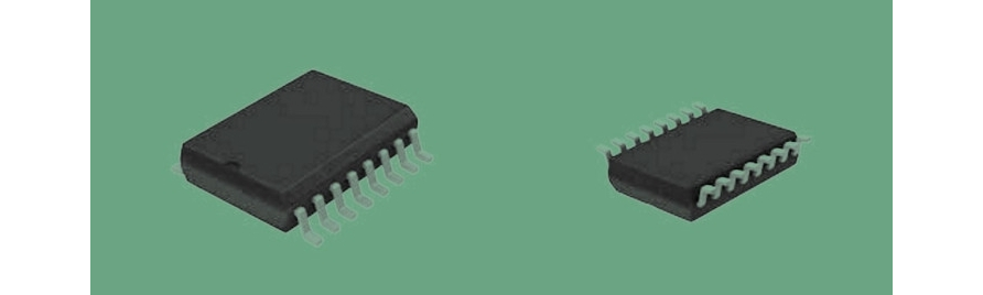
Shift register 74HC165.