3.2. Using Electrical Rules Checking in National
Instruments Multisim*
Electrical Rules Check (ERC)
The Electrical Rules Check creates and displays a report detailing connection errors (such as an output pin connected to a power pin) and unconnected pins. Once the circuit is wired, check the connections for correctness based on the rules set up in the Electrical Rules Check dialog box.
Depending on your circuit, you may wish to have warnings issued if some types of connections are present, error messages for other connection types, and no warnings or errors for other connections. You control the type of connections that are reported when ERC is done by setting up the rules in the grid found in the ERC Rules tab of the Electrical Rules Check dialog box.
ERC may be run over an entire design, or only across certain areas of a design. When an ERC is run, any anomalies are reported into a results pane at the bottom of the screen and the circuit is annotated with circular error markers. Clicking on an error will center and zoom on the error location.
The ERC Options tab and ERC Rules tab are used to configure the ERC.
To run the electrical rules check:
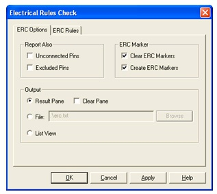
Figure 3.3.
ERC Options Tab
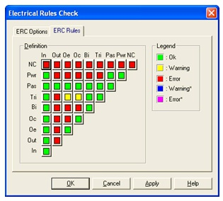
Figure 3.4.
ERC Rules Tab