Chapter 2. Schematic Capture
2.1. Electrical and Electronic Components Available in
National Instruments Multisim*
Components
Components Overview
Components comprise the basis for any schematic. A component is any part that can be placed onto the schematic. Multisim defines two broad categories of parts: real and virtual. It is important to understand the difference between these parts, in order to fully utilize their advantages.
Real components can be differentiated from virtual parts because real components have a specific value that cannot be changed, and a PCB footprint.
Virtual components are simulation-only components, which can be assigned user-defined characteristics. For example, a virtual resistor can take on any resistance (such as 3.86654 Ohms). Virtual components help designers to check calculations by simulating designs with precise component values. Virtual components can also be idealized components such as the 4-pin Hex display shown in Figure 1.
Multisim also provides other classifications of components: analog, digital, mixed-mode, animated, interactive, multisection digital, electromechanical, and radio-frequency (RF) components.
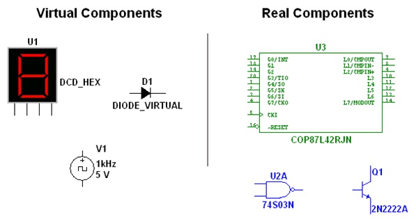
Figure 2.1.
Various Component Symbols: 7-Segment Display, Diode D1, Voltage Source V1, NAND gate U2A, Microcontroller U3 and Transistor Q1
Interactive Components
Multisim provides a method for interacting with certain components that are placed on the schematic. Changes to these components will affect the simulation results on-the-fly. Components are controlled by pressing the key listed beside the component.
For the components shown in Figure 2 below, pressing the A keywill increase the resistance of the potentiometer toward 100% of the shown value (1kΩ); to decrease the resistance, hold the Shift key then press the A key. Pressing the Spacebar will toggle the switch to be either closed or open.
The keyboard shortcut key can be changed by double-clicking on the component, and choosing the desired key from the drop-down box as shown below.
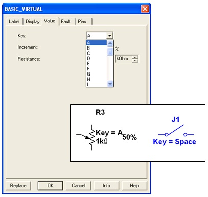
Figure 2.2.
Examples Interactive Components
Component Characteristics
The following fields are visible from the Component Browser.
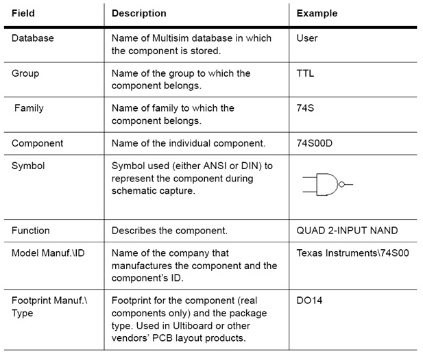
Figure 2.3.
Component Information
The Component Browser
The Component Browser is used to select components for placement onto the schematic. To access the Component Browser, click on any icon in the parts bin, or select Place/Component. The default keyboard shortcut to place a component is Ctrl-W.Double-click on the desired component to place it on the schematic. The component will “ghost” the mouse cursor until the left mouse button is clicked again to place the component.

Figure 2.4.
The Parts Bin or Component Toolbar
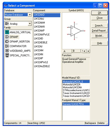
Figure 2.5.
The Component Browser
To search this view, simply start typing the name of the desired component, and the browser will automatically display matching candidate parts. Optionally, for a more detailed search, click on the Search button.
The Component Browser shows the current database in which the displayed parts are stored. Multisim organizes the parts by group, and family. The browser also shows the symbol, a description of the component in the Function field, the model, and the footprint / manufacturer.
The wildcard character ‘’can be used to match any set of characters. For example “LM78” would match components “LM*AD” would return both “LM101AD” and “LM108AD”, among others.
Note:Any component may have multiple models associated with it. Each model may account for varying physical characteristics of the component. For example, the LM358M opamp has five visible pins, but only three of them are used in one model, ignoring the power supply terminals. More information about models can be found by selecting the desired model from the Model Manuf.\ID field, and click on the Model button.
Databases
There are three levels of database provided by Multisim:
Database management tools are supplied in order to move components between databases, merge databases, and edit them. All the databases are divided into groups and then into families within those groups. When a designer chooses a component from the database and drops it onto the circuit, a copy of the component is placed onto the circuit. Any edits made to the component in the circuit do not affect the original database copy.
Edits made to the component in the database do not affect the previously placed components, but will affect all subsequently placed components of that type. When a circuit is saved, component information is saved in the Multisim file. On load, the user has the option to keep the loaded parts as is, to make copies to place into their user or corporate database, or to update similarly-named components with the latest values from the database. Note: The Database Manager can be opened by selecting Tools/Database/Database Manager. To edit Master Database parts, copy them to the User or Corporate Database.
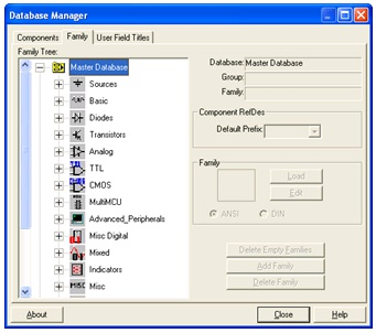
Figure 2.6.
Database Manager
Creating Custom Components
Multisim includes the ability to create and edit components to satisfy the needs of any design. The two methods available are the Component Wizard, and the Component Properties dialog box.
To access the Component Wizard, select Tools/Component Wizard. The component wizard allows designers to enter all pertinent component information, such as symbol, and SPICE model (Figure 7).
To access the Component Properties dialog box, double-click on a placed component, click on the Value tab, and click the Edit Component in DB button (Figure 8).
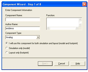
Figure 2.7.
Component Wizard
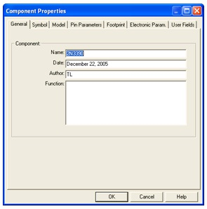
Figure 2.8.
Component Properties Dialog Box
More details on creating custom components are available in the helpfiles.