2.2. Exercise: Finding and Placing Components in
National Instruments Multisim*
Approximate time to complete: 10 minutes
This exercise has been designed to introduce users to the component browser. By the end of this exercise, you should be able to open the component browser, search and find components that you need, and learn more information about those components using the various fields of the browser.
Objectives
Procedure
1. Open a new schematic window (File/New/Schematic Capture).
2. Bring up the component browser by clicking on the Sources button of the Parts Bin (or Components Toolbar).
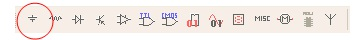
Figure 2.9.
1. Locate and place a Groundsymbol onto the schematic. It is found in the POWER_SOURCES Family.
2. Use the Searchtool to locate the Analog Devices OP297AZ.
(Hint:Try including a wildcard ‘’ in your search: “OP297”)
1. 1. How many sections does this chip have? __________
(Hint: Sections are lettered from A-Z)
1. 1. Should you place the opamp, you will have the option of choosing section A or B. You do not need to place the opamp at this time.
Figure 2.10.
1. 1. Use the Search tool to locate the 74S04D Hex Inverter.
2. When you place the inverter, you are given the option of placing any of the six inverters. Place the A gate. Notice that you now have the option of placing a new chip, or continuing to place gates of the existing U1.
3. Place another “A” gate. What is the default reference designator for this new inverter? ________