Structure Analytics
RailTech System Architecture
 Option 1 : DAS at TCC (Traffic Control Centre) /* refer figure 7.1*/
Option 2 : DAS Task shared between TCC and train /* refer figure 7.2*/
Option 3 : DAS tasks mainly onboard /* refer figure 7.3*/
 Railway system
track side infrastructure
vehicle or rolling stock
Railway infrastructure assets
Railway rolling stock
Dr. Williams is focusing on the structure of emerging technologies related to logistics security. The new automotive DNA is expected to be developed through proper integration of electrical drives and connected vehicle technologies. The design principles are based on electrical drives with electrical motors for power, renewable solar energy for battery charging and electronic systems for control. Hybrid EVs may use batteries and electric motors to improve the efficiency of mechanically driven vehicles. Smart vehicles are expected to be lighter, more conducive to electrical drives and renewable sources of energy to avoid air pollution. The computing schema should be able to estimate price and incentives for regulating demand and supply of electrical energy. Smart vehicles should be able to communicate wirelessly with each other and with roadway infrastructure and activities through global positioning system (GPS) technology and digital maps. Intelligent vehicle-to-vehicle (V2V) communication protocols should be able to avoid collision and crashes.
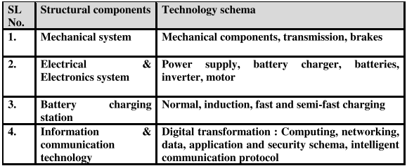
Table 7.1 : Structural analysis of electrical and hybrid vehicles
The topology of smart vehicles has been analyzed in terms of a set of sub-systems or modules, connectivity, type of connections, layers, interfaces between layers and organization of layers. The structure of EVs has three major components: mechanical system (e.g. brakes, wheel), electrical and electronics system (e.g. battery charging) and information & communication systems (e.g. driver advice system) [Table 8.1]. The sensors collect data from various systems and provide the inputs to DAS. DAS analyzes the sensed data and shows the output (e.g. alerts, advice) to the driver. Figure 8.5 shows typical structure of a hybrid EV.
It is essential to adopt a new automotive DNA which can transform the design principles of smart vehicles. The structure of traditional vehicles is mechanically driven and powered by ICE, energized by petrol and diesel, mechanical control system and operated in standalone mode. The new structure is expected to be more flexible, automated and simple to use. Another important part of the structure is mobile Internet; it is the backbone of communication schema which should enable the vehicles to share real-time and location-specific big data for optimal traffic management, minimal and more predictable travel time and no distraction of driving. The vehicles should be integrated with IoT and may be considered as nodes in mobile networks. The structure is expected to be less expensive to own and operate and should have light weight and less space. The integration of a set of transformative ideas should optimize the benefits, positive impacts and side effects in terms of design direction, energy, environment, safety, congestion and access inequality. These enabling technologies have been getting matured and converged gradually for practically feasible and large scale production. Common components of hybrid vehicle are power supply, normal, onboard and quick charging system, drive battery, inverter, motor, transmission and driving, regenerative braking and electricity generation system.
Smart Batteries: Smart batteries are an essential part of electrical and hybrid vehicles; let us explore and analyze the scope, system, security and strategy of smart batteries for EVs. Solid State Batteries (SSB) may be the future of EVs. Alternatively, EVs can use batteries having Li-ion, Ni-metal hydride (NiMH) and electric double layers ultra capacitors led by Li-ions. SSB is an emerging technology that uses solid electrodes and solid electrolyte such as ceramics (oxides, sulfides and phosphates), glass and solid polymers. Solid state batteries are safer with higher energy densities but at higher cost. Li-ion batteries use liquid or polymer electrolytes. SSB is generally used in pacemakers, RFID and wearable devices. Presently, the technology of SSB is being developed at Tesla, Toyota, Dyson (Sakti 3), Caterpillar (Fisker), Swiss Fraunhofer institute, Cambridge University; the technology has been diffusing globally. Toyota has planned to use solid state batteries in EVs by 2020. The challenge is to explore a solid conductive material fit for large batteries. Solid Power and Volkswagen are also investing to build high capacity manufacturing plants of SSB.
The next interesting issue is structure of RailTech system. The topology of technology should be analyzed in terms of nodes, connectivity, type of connections, layers, interfaces between layers and organization of layers. RailTech structure has three major components: trackside infrastructure, rolling stock or vehicle and driver advice system. Dr. Williams and Dr. Yokoo are giving the basic overview of rolling stock, infrastructure and the outcome of SWOT analysis of various types of DAS architectures. The sensors collect data from the track and rolling stock and provide the inputs to DAS. DAS analyzes the sensed data and shows the output (e.g. alerts, advice, recommendations) to the driver and traffic control centre (TCC).
SWOT Analysis on various DAS architectures : It is essential to analyze strength, weakness, opportunities and threats of RailTech innovation. There are opportunities of growth of the technology in various types of train services such as metro rail, local train and long distance train. But, the technological innovation may face various types of threats such as complexity, integration and digital transformation through sensors, information and communication technologies. It is hard to integrate the mechanical and information systems physically. Let us analyze three different types of system architectures in figures 7.1, 7.2 and 7.3. We have extended these architectures by incorporating the concept of real-time fault diagnostics. In each system architecture, the basic building blocks of RTFD are three analytics i.e. graph analytics (GA), fault tree analytics (FTA) and failure mode effects analytics (FMEA); the output of these analytics is fed to DAS. The core components of GA include control, resources and data flow analytics. In figure 7.1, DAS intelligence is deployed at TCC and the onboard system only displays advice information to the driver. The system can be implemented using existing driver interface without any additional system in the train. But, the scope of data displayed and dynamic update of compensating feedback to the driver is limited. This is an interesting practical and economic solution for possible DAS rollout in future.
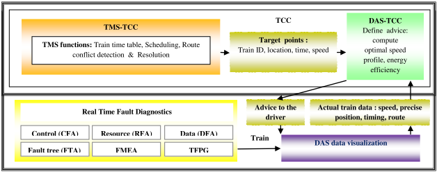
Figure 7.1 : DAS tasks done at Traffic Control Centre (TCC)
In figure 7.2, DAS intelligence is shared between TCC and train. TCC computes various critical parameters like previous architecture. DAS definitions and displays are done onboard. The solution optimizes the exchange of information between TCC and onboard in real-time. But, the advice can be poor if the real characteristics of the train system differ significantly from the characteristics known by TCC. The computation should be done correctly where it is easier to access the required data. In figure 7.3, DAS tasks are mainly onboard. DAS intelligence is implemented in the train. TCC computes a set of functions as mentioned previously. It can adjust speed and optimizes energy to drive the train based on advanced algorithms. The cost of communication between TCC and the train is reduced. But, there is risk of consistency of local optimization.
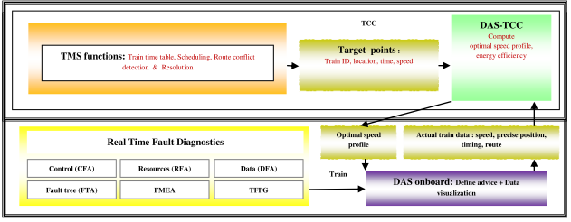
Figure 7.2: DAS tasks shared between the train and traffic control centre (TCC)
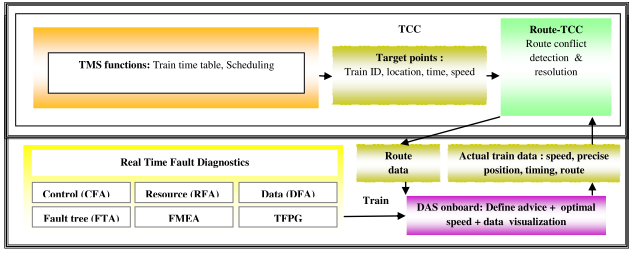
Figure 7.3 : DAS tasks mainly onboard in the train
Computing schema : This schema performs data processing task with the support of algorithmic intelligence. There may be various options for computing schema such as data processing only at TCC, data processing in a standalone system, data processing integrated with DMI, data processing integrated with third party applications (e.g. communication, position services), data processing integrated with train management system. In case of option 1, the processing takes place at the TCC and DAS only receives advice and displays it to the driver. It involves installation of minimum equipment on the train. Onboard stand-alone system requires a dedicated processing unit at a suitable location of the train. This option requires dedicated space and connections but can be installed through minimum interaction with cab and other onboard systems. Another option is to integrate data processing unit with driver machine interface. It reduces the number of modules to be installed but the maintenance task may be difficult. Another option is to integrate data processing unit with other applications (e.g. positioning, communication) through shared services. The computing schema performs various types of tasks such as tracking train movement, prediction of future train movement, conflicts detection and resolution, finding new target train timings to avoid conflicts and estimation of speed profiles and choice of advice to the driver.
Networking or communication schema : This schema controls exchange of data between traffic control centre, trackside and train through various types of communication options such as 3G/GPRS/4G data communication network, with or without integral antenna, 3G/GPRS/4G data to a communications gateway on the train, GSM-R text messaging and ERTMS/ETCS data communications. Another interesting issue communication through SMS between TCC and DAS. In case of 3G/GPRS/4G to DAS with built-in antenna, data communications to moving trains is provided via public telecom providers through GPRS, 3G and 4G by mounting data terminal within DAS equipment on the train with an integral aerial. No external connection is required to DAS but there may be poor communication coverage in several zones and electromagnetic compatibility problems (EMC). In case of 3G/GPRS/4G to DAS with external antenna, DAS with integral data terminal is permanently installed on a train. The only external connection is the antenna. The schema of 3G/GPRS/4G to a communications gateway onboard requires the existence of a shared communications server on each train integrated with a shared positioning system. .It is a costly option though it avoids installation of antenna over train roof. These schemes can use dedicated railway GSM-R network and public networks. It is an open agenda whether it is possible to adopt smartphones using 5G / 6G / 7G / 8G wireless communication schema with high speed of data exchange and also Internet of Thing (IoT) for sophisticated driver advice system in future.
Application schema: A simple DAS may provide predefined timetable information and other generic advice on paper or on a screen. It may be stand alone onboard applications with timetable information and other critical data loaded into the system, independently of the traffic management system. A complex DAS may provide the driver with dynamic advice on how to drive the train as per predefined timetable. The onboard advisory component receives pre-planned timetable, route and train related information from existing traffic management system and computes advice dynamically as per the behaviour of the driver. A sophisticated DAS may provide intelligent advice to the driver of a train based on real time traffic plan. The basic objective of the system is to optimize traffic flow for the railway network by dynamically adjusting the timetable to avoid conflicts. The onboard advisory component is linked to a real-time traffic management system that can calculate new train timings to avoid conflicts and communicate them to the driver.
One of the key components of DAS is Driver Machine Interface (DMI). The driver of the running train should be able to see it regularly; it should be positioned in his field of vision on or around the cab desk. There may be various options of DMI such as portable device on the cab desk, dedicated DAS-DMI permanently fitted, integrated with ERTMS/ETCS DMI, integrated with TMS DMI, integrated with GSM-R DMI. DMI system may be implemented in a portable device carried by the driver or it may linked with other parts through wired or wireless link. It incurs minimum hardware cost and it is possible to replace faulty unit easily. But, the portable device may be vulnerable to mismanagement, loss or damage. Another possible option is to permanently modify the dashboard to accept a dedicated display screen for DAS. The screen size and information display can be optimized for the application but there are space constraints. Another important component of DAS is train positioning system to determine the location of a train in real-time so that DAS can provide correct speed advice. There may be various options of train positioning system such as dedicated GNSS positioning system with or without integrated antenna, shared GNSS positioning system on the train, ERTMS/ETCS positioning system and train positioning with information available from TCC. GNSS with built-in antenna requires a dedicated GNSS positioning system with the support of satellite communication. Alternatively, GNSS can be connected with external antenna on the roof of the train.
Data schema : DAS can provide various types of information to the driver of a train such as explicit driving instructions (e.g. current speed target, time series analysis of train speed profile, advice to speed up or slow down), temporal information (e.g. : train running status, time delay optimized speed profile to realize time table), decision support information (e.g. gradient profile, energy usage, position of other trains, conflict, traffic congestion) and a set of monitored performance metrics (e.g. primary and secondary delays, capacity utilization, route conflicts, traffic congestion, signaling errors and real-time train scheduling and time table). One of the critical features of data schema is driver integration through human machine integration: alternative context of advice in terms of ‘follow-me’ or ‘trade-off’ method (what information is important to the driver) and alternative forms of advice (how the information is transformed to advice). DAS could guide various parameters such as distance or time interval updated advice, event updated advice, updated speed profile advice and contextual advice without target setting. There may be various forms of advice such as suggested speed based on difference in current speed and target speed, current target speed and duration and target; time keeping based on difference between the actual time at a particular point in the route and the target time, current target departure and arrival time, action on controls (e.g. brake pressure) and energy savings based on speed and time.