plants based on laser lidars (the Sayano-Shushenskaya HPP, 2006);
•
information-measurement complex for investigation and optimization of nonvolatile
memory of a new generation, to be introduced in 2010-2012, which is based on
switching the conductivity of unit nanoelements of sandwich structure (the Fujitsu and
the AMD, from 2004 through 2006);
•
information-measurement and hardware-software complexes of multiphase flow meter,
State Standard P 8.615-2005, for borehole flowmeter survey and optimal oil production
control (the NPK VT, TNK-BP, Tyumen, 2008).
These fundamental scientific results have made a considerable contribution to the
development of physical diagnostics, informatics of optoelectronic measurements, and
creation of many new information monitoring technologies to increase efficiency and safety,
which are successfully used in science and various fields of technology.
15. References
Anikin, Yu. ; Meledin, V. ; Naumov, I. ; Okulov, V. & Sadbakov, O. (2004). Investigation of
Pulsation Characteristics of Twisted Flow in Cubic Container. Tepl. Aeromekh., Vol.
11, No. 4, 2004, pp. 571-576.
Arbuzov, V. ; Belousov, P. ; Dubnistchev, Yu. ; Meledin, V. & Pavlov, V. (1992). Systems for
Optical Diagnostics of Dynamics and Phase Structure of Flows. Sib. Fis.-Tekh. Zh.,
No. 2, 1992, pp. 4-11.
Bakakin, G. ; Belousov, P. ; Dubnistchev, Yu. ; Meledin V. & Pohalchuk, Yu. (1997). Linear
Size Measurement by Photometry Optoelectronics. Opt. Instr. Data Proc., No. 4,
1997, pp. 1-6.
Belousov, P. & Meledin, V. (1985). A Simple Precision System for Remote Adjustment of
Lasers. Avtom., No. 5, 1985, pp. 105-106.
Belousov, P. ; Dubnistchev, Yu. & Meledin, V. (1988). Optical Velocity Meter on the Basis of
Semiconductor Laser. Kvant. Elektron., Vol. 15, No. 3, 1988, pp. 633-635.
Belousov, P. ; Dubnistchev, Yu. ; Meledin, V. & Pavlov, V. (1988). Laser Doppler
Anemometer with Time Selection of Orthogonal Components of Velocity Vector,
Avtom., No. 2, 1988, pp. 43-49.
396
Optoelectronic Devices and Properties
Belousov, P. ; Dubnistchev, Yu. ; Meledin, V. & Pavlov, V. (1990). Laser-Doppler
Anemometer with Adaptive Temporal Selection of the Velocity Vector. Opt. Appl.,
Vol. 20, No. 3, 1990, pp. 187-197. – a.
Belousov, P. ; Dubnistchev, Yu. & Meledin, V. (1990). Optical Velocimeters for Moving
Surfaces Using Gas and Semiconductor Lasers. Opt. Laser Techn., No. 6, 1990, pp.
335-339. – b.
Belousov, P. ; Dubnistchev, Yu. & Meledin, V. (1996). Optic Methods of Flows Studying by
Selecting of the Spatial-Temporal Structure of the Scattered Light, Proceedings of
SPIE. Laser Optics, pp. 147-153,Vol. 2773, 1996. – a.
Belousov, P. ; Dubnistchev, Yu. & Meledin, V. (1996). Optical Method for Measuring the Size
of Objects of Complex Shape. J. Opt. Techn., Vol. 63, No. 10, 1996, pp 794-796. – b.
Bolshov, L. ; Chudanov, V. ; Strizhov, V. ; Alekseenko, S. ; Meledin, V. & Pribaturin, N.
(2006). Best Estimate Methodology for Modeling Bubble Flows, Proc. ICONE 14:
14th Int. Conf. on Nuclear Engineering, Miami, Florida, USA, 2006.
Dubnistchev, Yu. ; Meledin, V. ; Zhuravel, F. & Pavlov, V. (1987). Laser Doppler
Anemometry with Selection of Optical Signal Coherent Component. Opt. Appl., Vol.
17, No. 2, 1987, pp. 71-80.
Dubnistchev, Yu. ; Meledin, V.; Naumov, I. & Sotnikov, V. (2000). Laser Diagnostic of the
Low-Velocity Swirled Flows. Optoelectr., Instr. Data Process., No. 5, 2000, pp. 30-39.
Dubnistchev, Yu. ; Meledin, V. ; Pavlov, V. & Yavorskii, N. (2003). Investigation of Energy
Separation in Vortex Tube of Square Section. Tepl. Aeromekh., No. 10, 2003.
Dvojnishnikov, S. ; Kulikov, D. ; Meledin, V. (2010). Optoelectronic method of noncontact
restoration of three-dimensional objects surface contour of the complex shape.
Metrology, No. 4. 2010, pp. 15-27.
Glavny, V. ; Bakakin, G. ; Meledin, V. ; Sadbakov, O. & Rakhmanov, V.V. (2006). A
Preprocessing Signal Module for Thermophysical Experiments. Prib. Tekh. Eksp.,
No. 2, 2007, pp. 166-168.
Kulikov, D. ; Anikin, J.; Dvojnishnikov, S. ; Meledin, V. (2010). Lazer technology for
definition of geometry of turbine rotor under load. Power stations, No. 7, 2010, pp.
39-43.
Meledin, V. (1995). Laser Devices for the Speed and Length Control of Rolling in Metallurgy.
Novosibirsk: Vortex Technologies, 1995, P/No. 9500001.
Meledin, V. ; Bakakin, G. & Naumov, I. (1999). A Wide-Aperture Precision Photodetector,
Instr. Exp. Techn., Vol. 42, No. 1, 1999, pp. 90-93.
Meledin, V. ; Bakakin, G. ; Naumov, I. & Sotnikov V. (1999). Laser Measuring Complex for
the Investigation of the Hydroimpulsive Devices, Proceedings 8th Int. Conf., Laser
Anemometry. Advanced and Applications, (Eds.: A.Cenedese, D.Pietrogiacomi), pp. 45-
54, Rome, Italy, September 6-8, 1999.
Meledin, V. ; Bakakin, G. ; Naumov, I. ; Pavlov, V. & Sotnikov V. (2000). Measurement of
Volumes of Skew Fields with Topologically Similar Parallel Cuts on Optical Images
on the Plane of Registration, Proceedings of SPIE ''Applications of Digital Image
Processing,'' Vol. 4115, pp. 669-679, 2000.
Meledin, V. ; Naumov, I. & Okulov, V. (2000). Influence of the Dissymmetry in Rotation
Fluids on the Vortex Core Precession and Spectral Characteristics of the Flows,
Proceedings 5th World Conf. on Experimental Heat Transfer, Fluid Mechanics and
Thermodynamics, pp. 2441-2446, Celata, G.P., et al., Eds., 2001, vol. 3,
Optoelectronic Measurements in Science and Innovative Industrial Technologies
397
Meledin, V. ; Naumov, I. & Sotnikov, V. (2001). Machine Vision System for Noncontact
Weighing, Proc. ISA 2001/IMEKO Special Millennium Sessions, Houston, Texas, USA,
2001, vol. 415, CD ISA, 2001.
Meledin, V.; Bakakin, G. ; Naumov, I. ; Pavlov, V. & Sotnikov, V. (2002). Real Time Machine
Vision System for Noncontact Measurements of the Masses of Free Falling Hot
Glass Drops, Current Research on Holography and Interferometric Methods for
Measurement of Object Properties: 2000-2002, Sel. Pap. SPIE, vol. 5134, pp. 139-149.
Meledin, V. ; Naumov, I.V. & Pavlov, V. (2002). An Experimental Investigation of the Flow
Produced in a Rectangular Container by Rotating Disk Using LDA, In : Optical
Methods for Data Processing in Heat and Fluid Flow, Chap. 3, Greated, C., Cosgrove, J.,
and Buick, J.M., Eds., pp. 25-37, Suffolk, UK: Professional Engineering Publishing,
2002.
Meledin, V. ; Okulov, V. & Naumov, I. (2003). Experimental Investigation of Twisted Flow
in Cubic Container. Techn. Phis., Vol. 48, No. 10, 2003, pp. 1249-1254.
Meledin, V. ; Pavlov, V. ; Tsvelodub, O. & Yavorskii, N. (2005). Poverkhnostnye volny v
zhidkom dielektrike (Surface Waves in Liquid Dielectric), Novosibirsk: Inst. of
Thermophysics, SB RAS, 2005, ISBN 5-89017-029-5. – a.
Meledin, V. ; Pavlov, V. ; Tsvelodub, O. & Yavorskii, N. (2005). Gravity-Capillary Waves on
the Surface of a Liquid Dielectric. Dokl. Phys., Vol. 50, No. 8, 2005, pp. 426-430. – b.
Meledin, V. (2006). Optoelectronic Computer Science in Energy Saving Technologies of
Industrial Corporations. Energy Saving Technologies in Scientific and Technical
Development for Industrial Corporations, Dortmund: DU Press, 2006, pp. 35-92.
Meledin, V. ; Anikin, Yu. ; Bakakin, G. ; Glavniy, V. ; Dvoinishnikov, S. & Kulikov, D.
(2006). Laser Doppler Semiconductor Anemometry of Vortex Flow behind the
Vane Wheel Rotor of the Water Turbine. Proc. SPIE Optical Methods of Flow
Investigation, Vol. 6262, pp. 123-133, 2006. – a.
Meledin, V. ; Anikin, Yu. ; Bakakin, G. ; Glavniy, V. ; Dvoinishnikov, S. & Kulikov, D. (2006).
Laser Doppler Diagnostic of Flow in Draft Tube behind Hydroturbine Runner,
Proc. 11th Int. Symp. on Unsteady Aerodynamics, Aeroacoustics and Aeroelasticity of
Turbomachnes, pp. 446-457, 2006, Moscow, CIAM, 2006. – b.
Meledin, V. ; Naumov, I. ; Kuznetsov, I. ; Morkin, O. & Mostovsky, N. (2006). Applying of
Specialized Optical Laser and Video Systems for Study of Three-Dimensional
Flows in Hydraulic Turbines, Proc. ''HYDRO-2006, Maximizing the Benefits of
Hydropower'' (Porto Carras, Greece, 2006), Aqua Media Int., pp. 1-8. – c.
Meledin, V. (2008). Informatics of Optoelectronic Measurements, Novosibirsk: Inst. of
Thermophysics, SB RAS, Russia.
Meledin, V. (2009). Informatics of Optoelectronic Measurements: Science and Innovative
Industrial Technologies. Journal of Engineering Thermophysics, Vol.18, No. 2, 2009,
pp. 99-128.
Meledin, V. (2010). 3D-diagnostic: it is simple, exact, accessible. First-hand Science, No. 2,
2010, pp. 23-24.
Pribaturin, N. ; Meledin, V. ; Bykov, M. ; Bezrukov, Y. & Onshin, V. (2006). Experimental
Investigation of Boiling Liquid Jet from a Pipeline Breaking, Proc. Int. Conf.
''Nuclear Energy for New Europe, '' Portoroz, Slovenia, 2007.
398
Optoelectronic Devices and Properties
Rakhmanov, V. ; Bakakin, G. ; Glavny, V. ; Meledin, V. & Naumov, I.V., (2006). A
Controllable High-Voltage Stabilized Power Source of Photoelectric Multiplier.
Instruments and Experimental Techniques, Vol.49, No. 5, 2006, pp.676-678.
Sadbakov, O. ; Meledin, V. ; Okulov, V. ; Naumov, I. ; Anikin, Yu. & Mostovskii, N. (2004).
Laser Doppler Diagnostics of Flow Structure Downstream of Hydroturbine Blade
Wheel at Optimal and Forced Loads. Tepl. Aeromekh., Vol. 11(4), 2004, pp. 577-582.
Part 4
Optoelectronic Measurements
in Frequency Domain
19
Optoelectronic Oscillators
Patrice Salzenstein
Centre National de la Recherche Scientifique (CNRS)
Franche Comté Electronique Mécanique Thermique Sciences
et Technologies (FEMTO-ST) Institute, Besançon
France
1. Introduction
Optoelectronic oscillator was invented in 1994 by Yao and Maleki, two researchers of the
NASA Jet Propulsion Laboratory [1]. The aim of this oscillator was first to generate
microwave signal with particulary low phase noise. The best results is -163 dBc/Hz at 10
kHz from a 10 GHz carrier. This system was initially developed for next generation radar to
replace microwave generators. Then new applications appear for time and frequency,
telecommunication, and navigation technology. Few years ago were published first
Optoelectronic Oscillators (OEO) with fiber loop [2,3], affordable for telecommunication
systems with adjustable frequency chosen with band filter value. But optical fiber are still
bulky because of their several km packaged lenghts and bring difficulties with temperature
control. However with a 4 km optical delay line in OEO, a 10 GHz oscillator prototype
exhibits a frequency flicker of 3.7x10⁻¹² (Allan deviation) and a phase noise lower than −140
dB.rad²/Hz at 10 kHz off the carrier [4]. The choice of integrating a mini-resonator is a way
to reach problems related to regulation of temperature and to work in limited volume,
necessary condition for building transportable sources. Optical fiber delay line is replaced
by a whispering gallery mode (WGM) optical mini-resonator in simple topology of OEO.
Optical signal can propagate by total internal reflection by WGM inside the crystal
resonator. One can then achieve a long equivalent delay line into the few millimeter
diameter optical mini-disk resonator. High quality factor were demonstrated [5]. In this
chapter are presented main principle of OEO. The interest to build such an oscillator is that
the expected microwave frequency that modulate the optic carrier can be increased without
1: X. S. Yao and L. Maleki, „High frequency optical subcarrier generator,“ Electronics Letters, 30(18),
1525 (1994)
2: A. Neyer, E. Voges, "High frequency electro optic oscillator using an integrated interferometer," Appl.
Phys. Lett. 40(1), 6-8 (1982)
3: X. S. Yao, L. Maleki, "Optoelectronic microwave oscillator," J. Opt. Soc. Am. B 13(8), 1725-1735 (1996) 4: K. Volyanskiy, J. Cussey, H. Tavernier, P. Salzenstein, G. Sauvage, L. Larger, and E. Rubiola,
"Applications of the optical fiber to the generation and measurement of low-phase-noise microwave
signals," J. Opt. Soc. Am. B 25(12), 2140-2150 (2008)
5: I. S. Grudinin, V. S. Ilchenko, L. Maleki, "Ultrahigh optical Q factors of crystalline resonators in the
linear regime," Phys. Rev. A 74, 063806(9) (2006)
402
Optoelectronic Devices and Properties
loosing stability. Main limitation are then in the ability to find stable enough components
such as high speed photo detectors.
2. How works an OEO
An OEO is an oscillator typically delivering a microwave signal. Purity of microwave signal
is achieved thanks to a delay line inserted into the loop. For example, a 4 km delay
corresponds to 20 µs time for optical energy to stay in the line. It is equivalent to a quality
factor Q=2πFT where F is the microwave frequency and T the delay induced by the delay
line. The continuous light energy comping from a laser is converted to microwave signal.
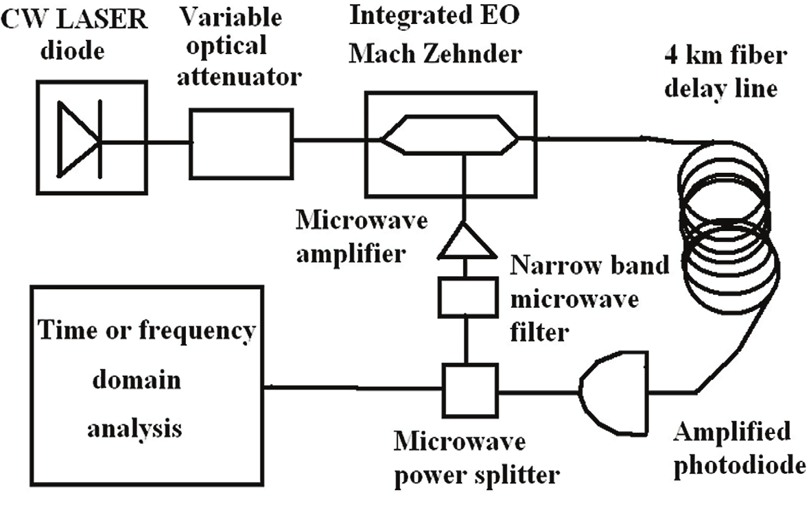
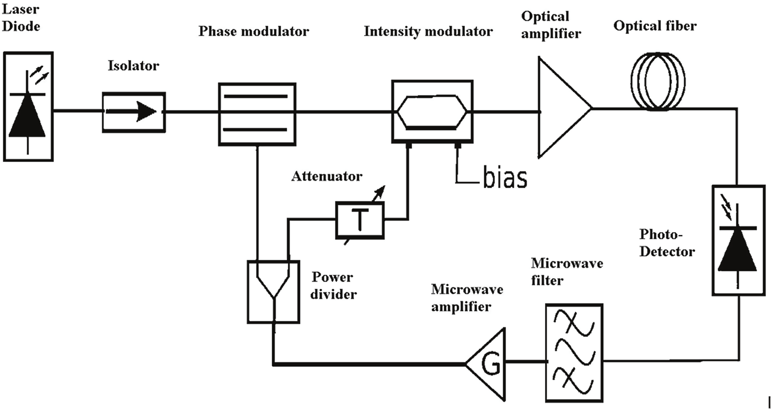
The loop of the oscillator consists in an optic and an electric part as systematized on the
following figure. Light from the laser goes through a modulator. The modulation
microwave signal comes from the output of the microwave amplifier after crossing a -10dB
directional coupler. Resonant element can be an optic fiber equivalent to a delay line. It can
also be an optical mini-resonator coupled to the optical fiber at the output of the phase
modulator. The microwave signal is amplified after the photodiode. OEO can have optic out
put with the modulated optical signal and microwave output through a directional coupler.
The oscillator consists of an amplifier of gain G and a feedback transfer function β(f) in a
closed loop. The gain G compensates for the losses, while β(f) selects the oscillation
frequency. Barkhausen condition gives G.β(f) = 1.
Fig. 1. Typical architecture of a fiber delay line OEO realized at FEMTO-ST institute
The optical fiber is a good choice for several reasons explained in this paragraph. A long
delay can be achieved, of 100 µs and more, thanks to the low loss (0.2 dB/km at 1.55 µm
and 0.35 dB/km at 1.31 µm). The frequency range is wide, at least of 40 GHz, still limited by
the optoelectronic components. The background noise is low, close to the limit imposed by
the shot noise and by the thermal noise at the detector output. The thermal sensitivity of the
delay (6.85x10⁻⁶/K) is a factor of 10 lower than the sapphire dielectric cavity at room
temperature. This resonator is considered the best ultra stable microwave reference. In
oscillators and phase-noise measurements the microwave frequency is the inverse of the
Optoelectronic Oscillators
403
delay. This means that the oscillator or the instrument can be tuned in steps of 10−5–10−6 of
the carrier frequency without degrading stability and spectral purity with frequency
synthesis. Finer-tuning is possible at a minimum cost in terms of stability and spectral
purity.
On the following figure is represented a typical topology of an OEO with a 4 km fiber delay
line.
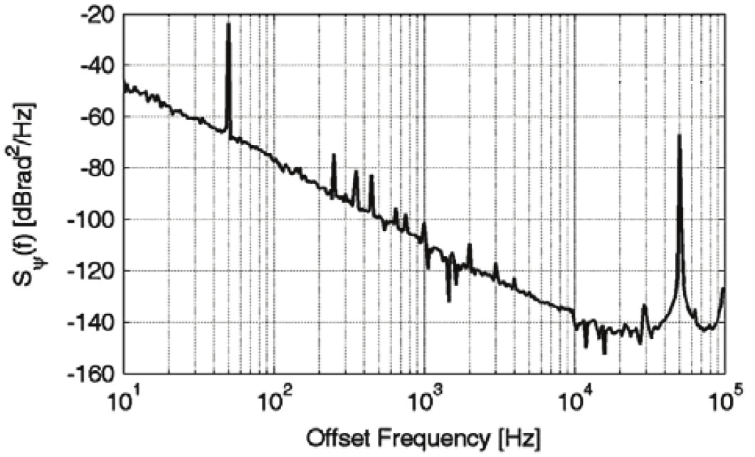
Fig. 2. Phase noise of an OEO realized at FEMTO-ST with a 4 km fiber delay line with a -145
dB.rad²/Hz noise floor at 10 kHz from a 10 GHz carrier
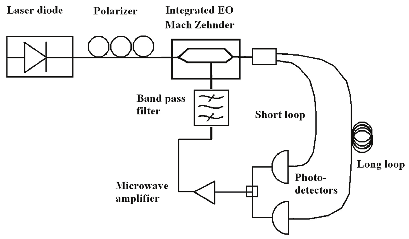
2. Examples of other topologies
With optical fiber several modes are in competitions. The use of two different loops enable
elimination of parasitic peaks. For illustration, a simple topology with two loops is
represented on figure 3. We design two optical ways detected by two different photo-
detectors. We schematically present on figure 4 how one loop can filter the signal.
A new approach for the generation of ultralow jitter optical pulses using optoelectronic
microwave oscillators was proposed. Short pulses are obtained through time-lens soliton-
assisted compression of sinusoidally modulated pre-pulses, which are self-started from a
conventional single-loop optoelectronic oscillator. The inherent ultra-low phase noise of
optoelectronic oscillators is converted into ultra-low timing jitter for the generated pulses.
Generation of 4.1 ps pulses along with a microwave whose phase noise is -140 dBc/Hz at 10
kHz from the 10 GHz carrier, with 2.7 fs jitter in the 1-10 kHz frequency band was
demonstrated [6]. Figure 5 represents such topology with compression of impulsion.
6: Y. K. Chembo, A. Hmima, P. A. Lacourt, L. Larger and J. M. Dudley, „Generation of Ultralow Jitter
Optical Pulses Using Optoelectronic Oscillators With Time-Lens Soliton-Assisted Compression,“ J. of
Lightwave Technology, 27(22), 5160 – 5167 (2009)
404
Optoelectronic Devices and Properties
Fig. 3. Double loop topology of OEO
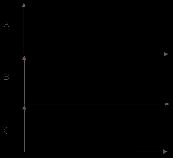
Fig. 4. A and B respectively represent long and short loops, one can see that peaks have been
filtered in the sum, C signal. Amplitude is represented versus frequency
Optoelectronic Oscillators
405
Fig. 5. Topology with compression of impulsion
3. Non linear approach for modelling the OEO
To study the behaviour of the system, a non linear approached was developed. It is based on
complex equation for the delay. A Neimark-Sacker bifurcation was demonstrated and
shown as a limitation for the performance of the system [7,8]. The possibility of multi-mode
propagation according to the starting conditions of the oscillators was also demonstrated [9].
They were experimentally confirmed with a remarkable precision. These results established
for the first time theoretical base of the spectral stability of the OEOs : noise floor and
characterization of peaks.
4. Exploring the choice of compact resonators
It is interesting to integer a compact resonator and forget a too long and temperature
sensitive optical delay line. With its tetragonal crystal and a good behaviour with risk of
water pollution, CaF2 is a good candidate but it has a bad reaction to mechanical shocks.
Resonators with MgF2 and fused silica are still interesting for their properties [10,11]. MgF2
can present low an inversion point around 80°C. Temperature variation of refractive index
7: Y. K. Chembo, L. Larger, H. Tavernier, R. Bendoula, E. Rubiola and P. Colet, „Dynamic instabilities of
microwaves generated with optoelectronic oscillators,“ Optics Letters, 32(17), 2571 (2007)
8: Y. K. Chembo, L. Larger and P. Colet, „Non linear dynamics and spectral stability of optoelectronic
microwave oscillators,“ IEEE J. Quantum Electron., 44(9), 858 (2008)
9: Y. K. Chembo, L. Larger, R. Bendoula and P. Colet, „Effect of gain and banwidth on the multimode
behaviour of optoelectronic microwave oscillators,“ Optics Express, 16(12), 9067 (2008)
10: P. Salzenstein, H. Tavernier, K. Volyanskiy, N. N. T. Kim, L. Larger, E. Rubiola, "Optical Mini-disk
resonator integrated into a compact optoelectronic oscillator," Acta Phys. Pol. A 116(4), 661-663 (2009)
11: H. Tavernier, P. Salzenstein, K. Volyanskiy, Y. K. Chembo and L. Larger, „Magnesium Fluoride
Whispering Gallery Mode Disk-Resonators for Microwave Photonics Applications,“ IEEE Photonics
Technology Letters, 22(22), 1629-1631 (2010)
406
Optoelectronic Devices and Properties
dne/dT of MgF2 is around zero in the range of 80°C (positive at lower temperatures and
negative at upper temperatures). It is particularly helpful to achieve stable oscillators as a
precise control of the temperature is a quasi-necessary condition to reach high stabilities.
Hardness of MgF2 and CaF2 is in the range of 6 Mohs and they have both good answer to
mechanical shocks that makes less difficult fabrication of mini-disk with these materials.
There crystal class is very different as MgF2 crystal is tetragonal and fused silica is non
crystalline, and if MgF2 is not sensitive to water pollution, it is necessary to have special
treatments to minimize H2O inclusion in fused silica [12]. These two material are relatively easy
to manipulate without damaging the surface. A special equipment must be developed for
manufacturing resonator. A dedicated polishing machine affords small eccentricity and a
precision adapter. System is hold on air bearing support to mechanically prevent influence of
vibration on the surface of the external tore surface of the mini-disk resonator. Process is
started from an initial crystal optical windows of about 6 mm diameter and 500 µm thickness
for X-band applications. The coupling zone has to be reduced to less than 50 µm, that's why
two 20 degrees angle bevels can be performed on the disk to form a sharp edge. We need a
very good optical quality with very low and regular roughness all around the torical surface of
the disk periphery. Powders with decreasing grain size are used. One can also achieve spheric
resonators from electric flash in a fibber to perform spheric profile. Some methods exist to
choose similar diameters for microspheres, based on the choice of similar diameters in the
used powder. Advantage of spheres is to be free with polishing process, one disadvantage
consist in the dispersion in the periphery, and difficulty to evacuate temperature.
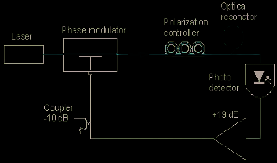
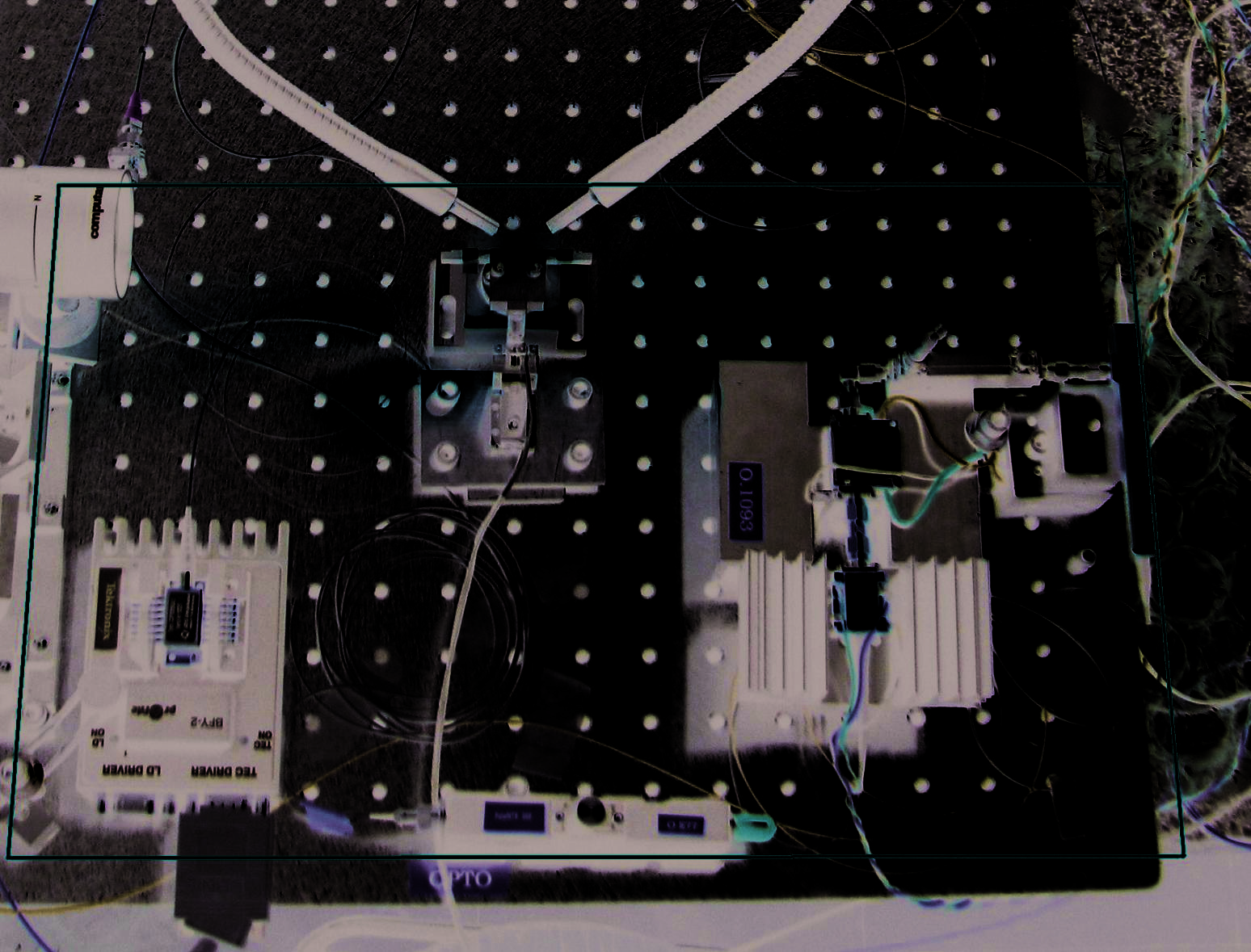
Fig. 6. Typical architecture of an optical resonator based OEO realized at FEMTO-ST institute
In order to introduce into the loop the fabricated resonator, it has to be coupled to the
optical light coming from a fiber. Best way to couple is certainly to to use a cut optical fibre
through a prism. But a good reproducible way in a lab is to use a tapered fibber glued on a
holder. Holder alloy and geometry match the thermal expansion of the glass.
For measuring the resonance [13], one uses the signal from a tunable laser diode . Fast digital
real time oscilloscope permits the analysis of the very sharp phenomena at peak resonance.
12: V. G. Plotnichenko, V. O. Sokolov, and E. M. Dianov, "Hydroxyl Groups in High-Purity Silica Glass,"
Inorganic Materials, 36(4), 404-410 (2000)
13: H. Tavernier, N. N. T. Kim, P. Feron, R. Bendoula, P. Salzenstein, E. Rubiola, L. Larger, "Optical disk
resonators with micro-wave free spectral range for optoelectronic oscillator," Proc. of the 22nd
European Time and Frequency Forum - Toulouse, France, paper FPE-0179 (2008)
Optoelectronic Oscillators
407
It is necessary to use a high speed resolution oscilloscope for the analysis of very short