where J = (J1, J2), with J1 (q) ∈ Rr,r, J2 (q) ∈ Rr, δ. The independent coordinates can be chosen so that J2 is full rank, and the generalized velocities are
(4)


Redundant Actuation of Parallel Manipulators
93
F is an orthogonal complement of J, i.e. JF ≡ 0. The accelerations follow with
q = F q 2 +
F q 2. The constituent feature of any PKM is that a moving platform, carrying an end-
effector (EE), is connected to the base by several (possibly identical) kinematic chains (limbs,
struts, legs) containing actuated joints. The EE is represented by an EE-frame. The
configuration of the EE-frame w.r.t. a inertial (world) frame is represented by C∈ SE (3). The
EE-map f E : Vn → SE (3), gives the EE-configuration C = f E (q) in the configuration q. The workspace of the PKM is
(5)
The EE-Jacobian JE (q) : TqVn → se (3) yields the EE-twist V = JE (q) q , in terms of the state of the PKM. If τ ∈ se* (3) is an EE-wrench, then Q = T
J τ
E is the corresponding vector of
generalized forces.
Now, the dynamics of a force-controlled holonomic constrained MBS with kinematical tree
structure is governed by the Lagrangian motion equations
(6)
where G is the generalized mass matrix, C q represents generalized Coriolis and centrifugal
forces, Q represents all remaining, including generalized potential forces, and u are the
generalized control forces. The Lagrange multipliers λ can be identified with the constraint
reactions in cut-joints.
For a PKM some of the possible control forces in u are identically zero, and only m control
forces corresponding to active joints are present. Denote with c ≡ ( c1, . . . , cm) the vector of
generalized control forces in the actuated joints. Let A be the relevant part of F so that
FT u = AT c. Projecting the Lagrangian equations (6) onto the configuration space V, with the
help of the orthogonal complement F and the relation (4), yields the Voronets equations
(Maisser, 1997; Papastavridis, 2002)
(7)
where
Clearly, only those c that are not in the kernel of AT are effective control forces. The system
(7) together with the kinematic constraints in (1) yield n differential equations in q ∈ Vn, that
completely determine the MBS dynamics.
Note that the motion equations are formulated in terms of minimal coordinates q ∈ Vn, for
the purpose of deriving an unconstrained control system. One has to be cautious, however,
since the removal of cut-joints can lead to dependent closure constraints that have no
physical meaning. These artifacts are merely due to the parameterization. Geometrically, V
94
Parallel Manipulators, Towards New Applications
is only a section of the ’complete’ configuration space, including cut-joint variables. This
issue is important for model based control, as pointed out in (Liu et al., 2003), since the
actual controller is built upon the model (7), i.e. using a certain V. In fact, it may be
necessary to switch between PKM models with different cut-joints.
5. The associated non-linear control systems
A PKM is a force-controlled holonomically constrained dynamical system, whose dynamics
is governed by (7). The control purpose is to manipulate the EE, which embodies the
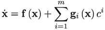
system’s primary output. A PKM can be regarded as a second order control-affine control
system on the configuration space V, which can be transformed to the first order control
system on the 2 n-dimensional state space TV
(8)
with state vector x := (q2, q 2). Therein
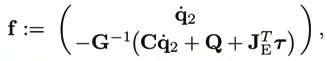
(9)
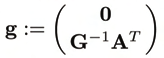
is the drift vector field, and the columns g i, i = 1, . . . , m ≤ n of
(10)
define the control vector fields, via which the control forces affect the system.
From a control point of view, one is interested in the controllability and observability of the
PKM. That is, one is concerned with whether the PKM can be steered between two given
configurations (Nijmeijer & van der Schaft).
6. Actuation and redundancy
The terms actuation and redundancy are differently used in the literature. In order clarify
this notion a stringent definition is given based on the above control system. The following
definitions refer to a regular configuration q, i.e. a configuration for which the orthogonal
complement F and its submatrix A has full rank in a neighborhood of q in V. The
dependence on q is omitted, and δ denotes the DOF.
Definition 1. The rank of the input vector field is called the degree of actuation (DOA)
α := rank (g) = rank (A) .
Redundant Actuation of Parallel Manipulators
95
If α < δ the PKM is underactuated and if α = δloc the PKM is full-actuated. The degree of
redundancy of the actuation is ρα := m − α. The PKM is called redundantly actuated if
ρα > 0 and nonredundantly actuated if ρα = 0.
Actuation refers to the effect that control forces have on the state change of a system. The
above definition is in accordance with this notion, though it refers to the ability to influence
the PKM’s acceleration. This is so because a PKM (as considered here) is a holonomically
constrained system, so that prescribing the acceleration also determines the velocity and
configuration, with known initial conditions. Actuation is a pointwise property, and the
DOA changes in singular configurations. The effect of the actuation on the motion is
described by the controllability of the system. This is a local property, i.e. considering the
effects over a small time (Nijmeijer & van der Schaft). Redundantly actuated PKM are
occasionally termed ’overactuated’. Notwithstanding that redundantly actuated PKM can be
underactuated, a full-actuated PKM is completely actuated, and an improvement is
impossible. Therefore, the term ’overactuation’ makes no sense.
7. Resolution of actuation redundancy
7.1 Inverse dynamics of redundantly full-actuated PKM
The first step in navigating PKM consists in task/motion planning and a subsequent
solution of the inverse kinematics, i.e. the determination of required actuator motions. The
inverse dynamics problem is to determine the actuator forces required for this motion to
take place. The DOA of a full-actuated PKM equals its DOF (δ = α). The number m = δ + ρ of
active drives of a redundantly full-actuated PKM exceeds its DOF by ρ. Without loss of
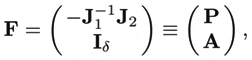
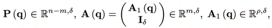
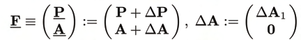
generality, the joint variables can be arranged as q ≡ (qp, qa), with qa ≡ (. . . , q2). Accordingly, the generalized control vector has the form u = (0, c), with c ≡ ( c 1, . . . , cm). The orthogonal complement takes on the form
(11)
where P contains the first n − m and A1 the remaining rows of − −1
J1 J2. A is full rank δ. The
kernel of AT is ρ-dimensional, so that (7) can not be uniquely solved for the controls c. As
consequence, 1) the load distribution among the drives is not unique, and 2) one can
generate control forces in the null-space of AT that have no effect on the motion, so-called
prestress.
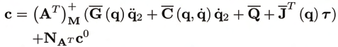
Let c0 ∈ Rm be a desired prestress vector, then a solution for the controls c such that
(c − c0)T M(c − c0) → min is
(12)

96
Parallel Manipulators, Towards New Applications
where (AT) + :=M−1A(ATM−1A)−1
is the weighed right pseudoinverse, and
M
N T := (I
A
m −(AT )+AT ) is a projector to the null-space of AT . Complete knowledge of the
system and the EE-load λ is assumed. M is a positive definite weighting matrix for the drive
forces.
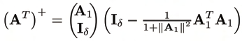
For the important case of simply redundant actuation (ρ= 1) a close form solution, with
M = I, was derived in (Müller, 2005). In this case A1 is a row vector, and
(13)
Note that no matrix inversion is necessary, which is numerically advantageous.
On the basis of a preceding path planing and inverse kinematics solution of redundantly
actuated PKM, the inverse dynamics is not unique and can take into account various goals.
Actuation redundancy can be used to reduce the load of individual drives by strategically
distributing the required control forces. On the other hand, the null-space components of the
control forces can be employed for ’secondary’ tasks.
7.2 Optimal distribution of control forces
An immediate application of the redundancy is a purposeful allocation of the control forces
(Kock & Schumacher, 1998). This is achieved via the weighing matrix M. Without prestress,
i.e. with c0 = 0, the inverse dynamics solution (12) is such that cTMc →min. Usually M is a
diagonal matrix, and its entries scale the control forces according to their drive
performances. The lower the force capability of a drive the higher its weight. E.g., one can
think of a lowpowered redundant drive, used to balance and reduce otherwise high force
peaks in the main drives.
Note, that these force considerations are essentially static, and do not take into account the
PKM dynamics. For highly dynamic applications, the driving power distribution may
significantly differ from the force distribution.
7.3 Backlash avoiding control
In (Müller, 2005; Valasek, 2002; Valasek, 2002) it was proposed to use internal prestress c0 to
avoid actuator backlash, which refers to situations, where the sign of the control forces
changes. One practical motivation for this is to eliminate the negative effects of joint
clearings, and another is rooted in the observation of DC motor hysteresis. Also, for tendon
driven PKM actuator signs must remain constant.
The main idea is to include the generation of internal prestress in the control scheme of the
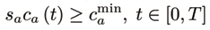
PKM. The condition for backlash free control is that the magnitude of each particular control
force ca remains above a certain level min
ca and that its sign remains constant during the
considered task with a duration T. Denote with sa ∈ {−1, 1} the required sign of ca, then the
condition
(14)
Redundant Actuation of Parallel Manipulators
97
must be satisfied with min
ca > 0.
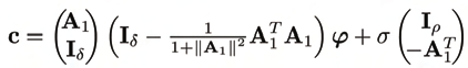
In (Müller, 2005) a method for backlash avoiding control of simply rendundantly actuated
PKM was presented. In this case AT has a one-dimensional null-space that can be
parameterized by a prestress parameter σ (t), so that
(15)
with ϕ := G (q)
q 2 + C (q, q ) q 2 + Q .
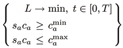
Given a prescribed trajectory qd ( t), the control problem at time instant ti consists in
determining the prestress parameter σ ( ti) such that (14) holds and an objective functional
L (qd ( ti) , σ ( ti)) is minimized. The latter can be the weighed sum of squared control forces or
the overall driving power. In summary the one-dimensional optimization problem
(16)
with c (q, q , q , σ) in (15), has to be solved at any time step. This can either be solved
independently at each time instant, or the σ can be approximated as a function of time,
which results in a smoother behavior.
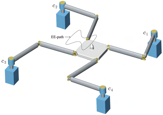
Figure 4. Planar 4RRR manipulator.
98
Parallel Manipulators, Towards New Applications
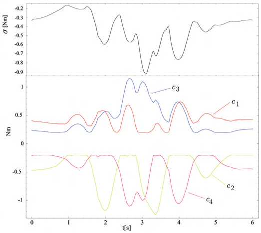
Figure 5. Prestress parameter and control torques for the EE motion in figure 4 with sign
vector s = (−1, 1,−1, 1).
For illustration purpose, we recall an example from (Müller, 2005), where the redundantly
full-actuated planer PKM in figure 4 is navigated along the shown EE-path with fixed EE
orientation. Figure 5 shows the drive torques, where a minimum drive torque of 0.2 Nm was
required for prestress, with sign vector (s a) = (−1, 1,−1, 1).
7.4 Stiffness control
Stiffness or impedance control has long been proposed and developed for serial
manipulators (Asada & Slotine, 1986). These concepts can straightforwardly be adopted for
non-redundantly actuated PKM, thanks to the identical structure of the motion equations.
Essentially, stiffness control (more precisely the control of the tangential stiffness since a
PKM is a highly non-linear dynamical system) aims to mimic the force-deflection properties
of an elastic medium, so that an applied EE-wrench causes an ’elastic’ evasive deflection.
This is achieved by generating control forces as reactions to joint motions caused by EE-
motions. It is thus the result of a control cycle, which operates in discrete time steps. The
actual behavior is therefore only ’elastic’ for sufficiently slow effects, due to the latency in
the force response to due to a perturbation.
Now, redundantly actuated PKM possesses the potential for another approach that does not
suffer from the control latency. Redundant actuation allows for the generation of prestress,
using controls in the null-space of AT. Since AT and thus N T are configuration dependent,
A
part of the null-space component of a given control vector c becomes effective when the
configuration is perturbed. Hence, there is an immediate! response to EE-deflection. In order
to exploit this effect, the control forces in the null-space of AT must be such that the change
of AT due to a EE-perturbation yields a desired EE-wrench. This was attempted in (Müller,
Redundant Actuation of Parallel Manipulators
99
2006; Yi et al., 1989). It turned out that, for the considered PKM, a large number of
redundant actuators is required for stable control of all stiffness components. This
requirement is eased if only some stiffness components are to be controlled. Moreover, so
far, stiffness control was not taken into account in the PKM design, and other novel PKM
structures may need lower actuator redundancy to control EE stiffness via prestress.
8. PKM control
Upon the motion equations (7), established non-linear control methods can be applied to
PKM, and shall exhibit the known stability properties. Model based motion control of
redundantly actuated PKM was addressed in (Cheng et al, 2003). It was proposed to adopt
the established computed torque and augmented PD control schemes, where perfect
knowledge of the PKM model as well as perfect measurement of position, velocity and
acceleration was presumed. The assumption of perfect measurements was abandoned in
(Garrido, 2004), and a standard PD control in conjunction with a velocity estimator was
proposed. In (Gourdeau et al., 1999) a computed torque control scheme without velocity
measurement was proposed. Common to the control methods proposed so far, is the
assumption of a perfect model. Robust control of redundantly actuated PKM has not yet
been attempted.
In the following we briefly recall the standard model bases control schemes and their
application to PKM control, and point out problems specific to redundantly actuated PKM
that arise in the presence of model uncertainties. For notational simplicity the weighting
matrix M = I is assumed.
8.1 Model-based control schemes
Two model-based control schemes frequently used for the control of robotic manipulators:
the augmented PD and the computed torque control (Asada & Slotine, 1986; Murray, et al.,
1993). The unaltered augmented PD control attains the form
(17)
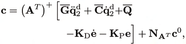
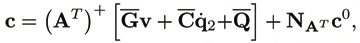
with the desired nominal path qd ( t), and the tracking error e ( t) := q ( t)−qd ( t) (Cheng et al., 2003). The computed torque control law adopted for PKM is
(18)
setting v := d
q2 −KD e −KPe. Perfect matching of model and plant presumed, both control
laws applied to (7) result in exponential trajectory tracking for sufficiently large gains KD
and KP, provided G is regular. The latter assumption fails in configuration space
singularities.


100
Parallel Manipulators, Towards New Applications
8.2 Model uncertainties
The aforementioned control laws yields exponential stability for the nominal system only.
Any real-life manipulator will differ from the nominal model used in the control scheme
due to inevitable model uncertainties. There is a plethora of methods for the estimation of
kinematic and other model parameters of serial manipulators, such as inertia, stiffness, and
friction. Adaptations of these algorithms to PKM were proposed in (Valasek, 2002). Friction
identification in particular was attempted in (Abdellatif et al., 2007).
A parameter estimation, whatsoever, will not achieve perfect matching of model and plant.
To tackle this uncertainties, a number of robust control schemes have been proposed for
serial manipulators. Robust control is still a field of active research, and we will not attempt
to develop a such for redundant PKM here. The interested reader is referred to (Asada &
Slotine, 1986) for the fundamentals. It is nevertheless instructive to investigate the effect of
model uncertainties. In contrast to non-redundant manipulators, where model uncertainties
cause incorrect positioning, geometric uncertainties of redundantly actuated PKM may
cause (possibly high) actuator loads that have no effect on the motion.
Deviations from the nominal geometry alter the geometric constraints and thus the
configuration space V. That is, a configuration q ∈ Vn that complies with the nominal
constraints will not do so for the uncertain system. If the variations are small, the PKM
configuration will still be expressible in terms of the independent coordinates q2. The
constraint Jacobian in (1) changes according to
(19)
Underlines indicate perturbed objects. For Δf small compared to f, and neglecting second
order terms of Δ J, yields
(20)
The perturbed orthogonal complement is then
(21)
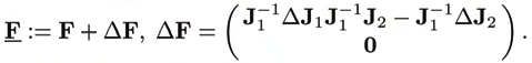
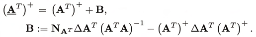
The splitting (11) according to active and passive joints yields
(22)
where ΔA comprises the last ρ = m − δ rows of −1
J1 ΔJ1 −1
J1 J2 − −1
J1 ΔJ2. Thus, the
pseudoinverse of AT is
(23)