1.1 Instantaneous twist and wrench capabilities
The instantaneous twist and wrench capability analyses are essential for the design and
performance evaluation of serial and parallel manipulators. An instantaneous twist is a
screw quantity that contains both angular and translational velocities of the end-effector, i.e.,
T
T T
V = {ω ; v } . Whereas, a wrench is a screw quantity that contains the forces and moments
acting on the end-effector, i.e.,
T
T T
F = {f ; m } . For a given pose, the required task of the end-
effector is to move with a desired twist and to sustain (or apply) a specific wrench. These
kinematic conditions are achieved with corresponding joint velocities ( q) and joint torques
(τ), respectively. The relationship between the task and joint spaces is defined by the well
known linear transformations:
x = J q
(1)
T
τ = J F
(2)
where J is referred to as the Jacobian matrix.
In addition, an extended problem can be formulated as the analysis of the maximum twist
or wrench that the end-effector can perform in the twist or wrench spaces, respectively. The
knowledge of maximum twist and wrench capabilities is an important tool for achieving the
optimum design of manipulators. For instance, by being able to graphically visualize the
twist and wrench capabilities, comparisons between different design parameters, such as the
actuator torque capabilities and the dimensions of the links, can be explored. Also, the
performance of an existing manipulator can be improved by identifying the optimal
capabilities based on the configuration of the branches and the pose of the end-effector.
This work focuses on the wrench capabilities of planar parallel manipulators (PPMs), the
geometric interpretation of their wrench polytopes, the derivation of wrench performance
indices, and how the inclusion of redundancy affects the performance of parallel
manipulators (PMs). The wrench capability analysis of a manipulator depends on its design,
posture, and actuator torque capabilities.
110
Parallel Manipulators, Towards New Applications
For a 3-degree-of-freedom (DOF) planar manipulator, the wrench F is a screw quantity that
contains the two components of the force on the plane ( fx and fy) and the moment normal to
the plane ( mz). The problem of finding the wrench capabilities of a manipulator involves the
forward static force equation
-T
(F = J τ) and the actuator output capabilities (τ To date,
i ).
three different approaches for determining wrench capabilities have been proposed in the
literature: constrained optimization, wrench ellipsoid, and wrench polytope.
1.2 Constrained optimization
In general, the constrained optimization approach involves: an objective function that
maximizes either the magnitude of the force f or the moment mz; one equality constraint
-T
(F = J τ) ; and a set of inequality constraints (τ
≤ τ ≤ τ
indicating the actuator output
i
i
i
),
min
max
capabilities. Kumar and Waldron (1988) investigated force distribution in redundantly-
actuated closed-loop kinematic chains and concluded that there would be zero internal
forces using the Moore-Penrose pseudo-inverse solution. Tao and Luh (1989) developed an
algorithm that determines the minimum torque required to sustain a common load between
two joint redundant cooperating manipulators. Nahon and Angeles (1992) described the
problem of a hand grasping an object as a redundantly-actuated kinematic chain. The
problem was formulated with both equality and inequality constraints and the torques were
found by minimizing the internal forces in the system using Quadratic Programming.
Buttolo and Hannaford (1995) analyzed the force capabilities of a redundant planar parallel
manipulator. Torques were optimized using the ∞-norm resulting in higher force
capabilities when compared to the pseudo-inverse solution. Nokleby et al. (2005) developed
a methodology to optimize the force capabilities of redundantly-actuated planar parallel
manipulators using an n-norm, for large values of n, and a scaling factor. Garg et al. (2007)
implemented this approach to spatial parallel manipulators.
This approach is usually slow due to the numerical nature of the algorithm and inaccuracies
due to the existence of local minima.
1.3 Wrench ellipsoid
The wrench ellipsoid approach is based on bounding the actuator torque vector by a unit
sphere T
τ τ ≤ 1. The torques are mapped into the wrench space with Eq.(2), yielding a force
ellipsoid T T
F JJ F ≤ 1. If Singular Value Decomposition (SVD) is applied to J i.e.,
T
J = UΣV ,
the principal axes of the ellipsoid can be determined as u σ where σ is the k th singular
k /
k
k
value and u is the k th column of matrix .
U These axes can be employed as wrench
k
performance indices of the manipulator. This approach was introduced by Yoshikawa (1985)
with the manipulability (twist) ellipsoid and proposed manipulability measurements. Also,
Yoshikawa (1990) presented the duality between the twist and wrench ellipsoids concluding
that axes of the ellipsoids coincide but their lengths are inversely proportional.
For cooperating manipulators, Chiacchio et al. (1996) presented a complete analysis of
wrench ellipsoids for multiple-arm systems, which involves external and internal forces. Lee
and Kim (1991) (velocity problem) and Chiacchio et al. (1997) (static force problem)
proposed to normalize the joint space variables (joint velocities and joint torques,
respectively) when the actuators do not produce the same output. As a result, the resulting
ellipsoid is defined as the pre-image of the unit sphere in the scaled joint variable space.
Wrench Capabilities of Planar Parallel Manipulators and their Effects Under Redundancy
111
The wrench ellipsoid approach can be implemented easily and the required computation is
immediate. However, this approach is an approximation because the joint torques are
normalized T
(τ τ ≤ 1) yielding a hypersphere in the torque space. The correct model of the
joint torques must be an m-dimensional parallelepiped in the torque space due to the nature
of the extreme torque capabilities of each actuator, i.e., τ
or τ
i
.
min
i
max
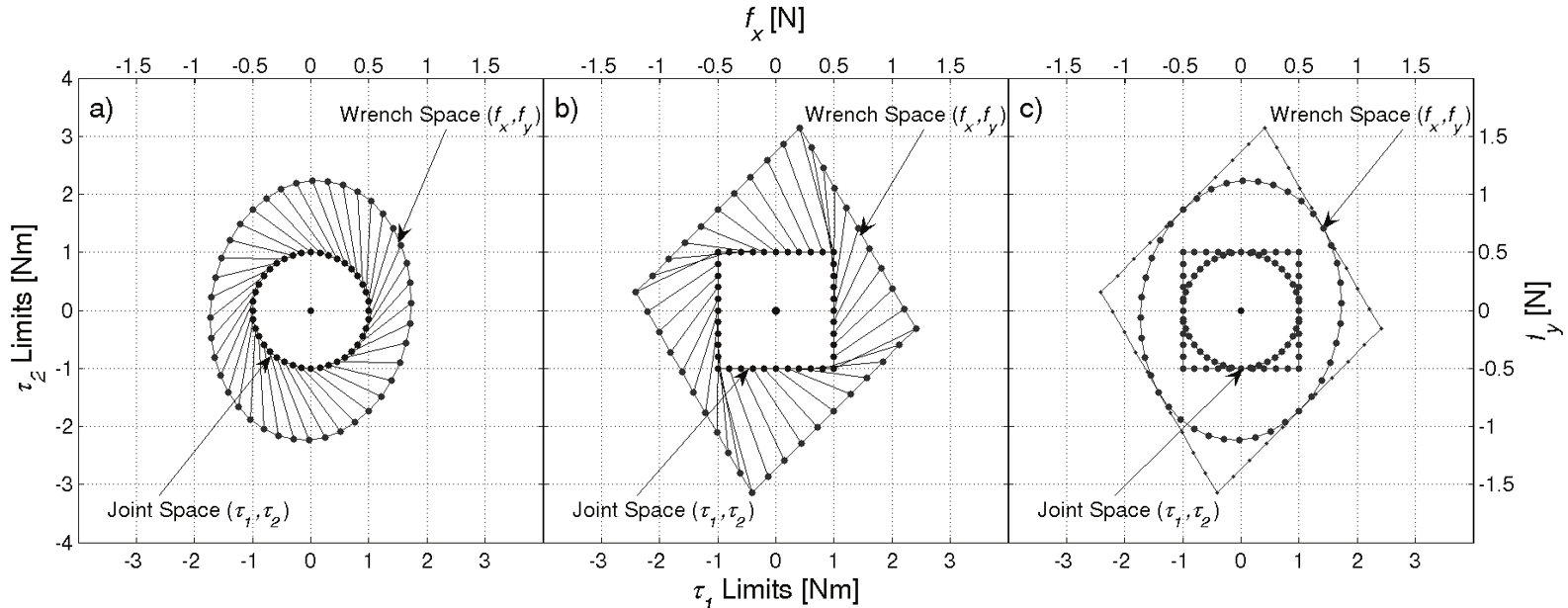
1.4 Wrench polytope
The wrench polytope approach considers the complete region in which the actuator can
operate. A comparison between the ellipsoid approach and the polytope approach is shown
in Fig. 1. Assume a manipulator with two actuated revolute joints whose extreme
capabilities are τ
= ± Nm, for i = 1, 2. Fig. 1a shows the generation of an ellipse (in
i
1
ext
general, an ellipsoid) as a result of mapping a circle (in general, a hypersphere). Fig. 1b
shows the generation of a polygon (in general, a polytope) as a result of mapping a square
(in general, a hypercube). Each plot contains two coordinate systems. The inner circle of Fig.
1a and the inner square of Fig. 1b describe the torque limits in the torque space (bottom and
left axes); whereas, the outer ellipse and polygon describe the wrench capabilities in the
wrench space (top and right axes). The lines that connect the inner to the outer shapes
illustrate the linear transformation. Note how the edges and vertices of the square and
polygon correspond in both spaces. The areas comprised by these geometrical shapes
represent the feasible capabilities in their corresponding spaces. The square is an exact
representation of the torque capabilities; while, the circle is an approximation. For example,
the upper-right vertex of the square is τ = τ = 1 Nm; although this torque combination is
1
2
feasible, the circle model does not include it. Thus, modeling the torque capabilities as a
square is better than as a circle. Fig. 1c shows how the circle and ellipse are inscribed within
the square and polygon, respectively. It is important to mention that the principal axes of
the ellipse are directed towards the vertices of the polygon.
Fig. 1. Mapping of ellipsoids and polytopes from the joint space to the task space.
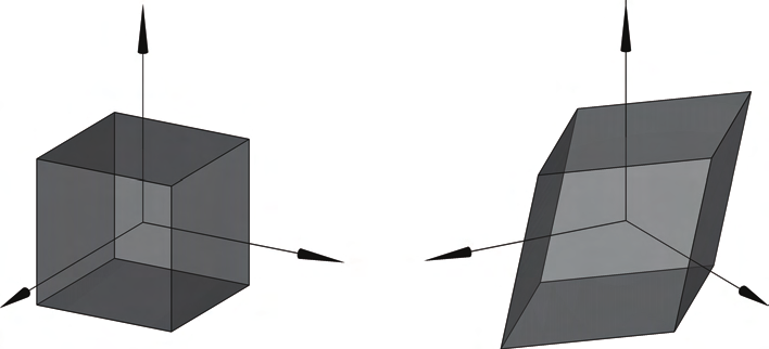
In general, each actuator torque defines an orthonormal axis in m
\ . The extremes of each
torque constrain the torque space with a pair of parallel planes along each axis. The feasible
region in which the manipulator can operate is bounded by these pairs of parallel planes
yielding an m-dimensional parallelepiped.
112
Parallel Manipulators, Towards New Applications
A linear transformation, such as the equation of the forward static force, Eq. (2), maps vector
τ from m
\ (joint torque space) to n
\ (wrench space).
Rockafellar (1997) studied the properties of convex polyhedral sets. From his analysis, the
following relationship is held through a linear transformation: Let τ be the m-dimensional
parallelepiped (a convex set) and -T
J be the linear transformation from m
\ to n
\ . Then the
resulting transformation -T
J τ leads to another convex polyhedral set (F) in n
\ and it
contains a finite number of facets.
Kokkinis and Paden (1989) introduced the concept of twist and wrench convex polytopes.
The analysis was applied to a single serial manipulator and to two cooperating
manipulators. Chiacchio et al. (1997) analyzed the wrench polytopes of redundant serial
manipulators. Finotello et al. (1998) introduced two sets of indices that can be implemented
to twist and wrench polytopes: the maximum isotropic value (MIV) and the maximum
available value (MAV). These indices will be discussed in detail in Section 4. For 6-DOF
manipulators, Finotello et al. (1998) proposed to analyze these indices with force and
moment as separate entities. Gallina et al. (2001) analyzed the manipulability of a 3-DOF
wire driven planar haptic device using polytopes. Lee and Shim (2004) expanded the
concept to dynamic manipulability of multiple cooperating manipulators resulting in
acceleration polytopes. Krut et al. (2004a) analyzed twist ellipsoids and polytopes in
redundant parallel manipulators and established performance indices. They showed that
there is another ellipsoid, besides the one derived with SVD, which is larger in volume and
is fully inscribed within the polytope. Krut et al. (2004b) also studied force performance
indices of redundant parallel manipulators and determined the isotropic wrench
workspaces of planar wire-driven manipulators with multiple actuated limbs. Firmani et al.
(2007a and 2007b) derived a set of wrench performance indices for PPMs.
2. Redundancy
2.1 Types of redundancy
Merlet (1996) described that the inclusion of redundancy may lead to improvements in
various analyses such as forward kinematics, singular configurations, optimal force control,
and calibration. Lee and Kim (1993) defined a redundant parallel manipulator as one that
has an infinite number of choices for either generating motion or resisting external forces.
Also, Lee and Kim (1993) presented an analysis of different types of redundancy. Ebrahimi
et al. (2007) classified redundancy into two categories: kinematic and actuation redundancy.
2.2 Kinematic redundancy
A manipulator is termed kinematically redundant when at least one of the branches can
have self-motion while keeping the mobile platform fixed. Thus, there is an infinite number
of possible solutions to the inverse displacement problem. This is the typical case of
redundant serial manipulators. For parallel manipulators, this redundancy happens when
the number of joints of at least one branch is greater than the number of joints that are
required to provide the desired mobility of the mobile platform. This type of redundancy
allows self-motion of the redundantly-jointed branch(es) improving the dexterity and
workspace of the manipulator. A draw back of this type of redundancy is the increase of
mass and/or inertia due to the addition of actuators on the mobile links. Despite the
redundancy, there is only one vector force per branch acting on the mobile platform. Thus,
Wrench Capabilities of Planar Parallel Manipulators and their Effects Under Redundancy
113
the load capability cannot be optimized, but as an alternative, the direction of the branch
forces can be optimized by changing the posture of the redundantly-jointed branch(es). With
this type of redundancy, each actuator can be manipulated independently and there are no
internal forces that could damage the device. Kinematic redundancy can be employed to
reduce or even eliminate singular configurations. Wang and Gosselin (2004) added an extra
revolute joint to one branch of the 3-RPR PPM yielding a RRPR-2RPR layout. The
singularity conditions were identified and the singularity loci were reduced. Ebrahimi et al.
(2007) proposed the 3-PRRR PPM, a layout that contains joint redundancy in every branch.
This manipulator can provide singularity free paths and obstacle avoidance by properly
manipulating the actuated joints.
2.3 Actuation redundancy
A parallel manipulator is termed redundantly actuated when an infinite number of resultant
force combinations can span the system of external forces. Thus, there is an infinite number
of solutions to the inverse static force problem. The implementation of this redundancy
requires a reliable control system because a small variation in the displacement may cause
severe damage to the manipulator. There are two types of actuation redundancy: in-branch
redundancy and branch redundancy.
In-Branch Redundancy. Passive joints are replaced by active joints. For every redundant
actuator added within branch(es), the number of the forces resisting an external load is
augmented by one. This type of redundancy can be easily incorporated into an existing
device. Nokleby et al. (2005) developed a methodology to optimize the force capabilities of
the 3-RRR PPM using a high norm and a scaling factor. Zibil et al. (2007) determined the
force capabilities of the 3-RRR PPM by using an analytical based method. Nokleby et al.
(2007a) investigated the force-moment capabilities of different in-branch redundancy
architectures. With in-branch redundancy, there is no change in the workspace of the
manipulator. However, there is an increase of mass and/or inertia due to the addition of
actuators. Firmani & Podhorodeski (2004) eliminated families of singular configurations by
adding a redundant actuator to the 3-RRR PPM, yielding a RRR-2RRR layout.
Branch Redundancy. An additional actuated branch is added to the system. For every
additional actuated branch incorporated into the system, the number of forces acting on the
mobile platform is augmented by one. Buttolo and Hannaford (1995) designed and analyzed
the force capabilities of a 2-DOF 3-RRR PPM haptic device, where all three branches are
pinned together. Gallina et al. (2001) analyzed the maximum force and moment of a four-
wire driven 3-DOF planar haptic device. Krut et al. (2004a) implemented performance
indices, previously developed in Krut et al. (2004b) for velocity analysis, to 2-DOF parallel
wire-driven manipulators. Different analyses of multi-actuated wires were considered.
Nokleby et al. (2007b) investigated the force-moment capabilities of the 4-RRR, 4-RPR, and
4-PRR PPMs. Firmani & Podhorodeski (2005) presented a methodology to identify singular
configurations of planar parallel manipulators with redundant branches. The main problem
of manipulators with branch redundancy is the reduction of their dexterity and workspace.
3. Wrench polytope analysis
3.1 Joint space parallelepiped
Let n be the DOF of the task space coordinates and m be the number of actuated joints. The
ith joint torque variable, which is bounded by τ
and τ
can be represented in the joint
i
,
min
i
max
114
Parallel Manipulators, Towards New Applications
torque space as two parallel planes in m
\ . With m joints, there are 2m planes or m pairs of
parallel planes. An m- dimensional parallelepiped is formed with the combination of all of
these parallel planes yielding the region of joint torque capabilities. If all the torque
capabilities were equal, the m-dimensional parallelepiped would result in a hypercube.
Also, if the magnitude of the extreme torques were equal, i.e., τ
= τ
, the
mi
i n
m
i ax
parallelepiped would be centro-symmetric; otherwise it would be skewed.
A vertex of the m-dimensional parallelepiped defines the intersection of m extreme torque
planes. Thus, a vertex occurs when all joint torques are at their extreme capabilities, i.e.,
T
v = ⎡τ
τ
τ
⎤
(3)
j
...
⎣ 1
2
ext
ext
ext
m
⎦
where τ
denotes the extreme capabilities of the ith actuator, i.e., τ
or τ
The total
i
.
ext
i
min
i
max
number of vertices in the m-dimensional parallelepiped is v = 2 m (Chiacchio et al., 1997).
Tm
3.2 Linear transformation
Visvanathan and Milor (1986) investigated the problems in analog integrated circuits while
accounting for the tolerance variations of the principal process parameters. The problem
involved the mapping of a parallelepiped under a linear transformation. Their mathematical
formulation is similar to the one used for analyzing wrench capabilities in this work. Let the
coordinates of the vertices of a parallelepiped in m
\ be v for j = 1, ..., 2 .
m Through a
j ,
linear transformation from m
\ to n
\ , such as
-T
F = J ,
τ the m-dimensional parallelepiped
becomes a polytope (Visvanathan and Milor, 1986). A polytope is a convex region, i.e., any
two points inside the polytope can be connected by a line that completely fits inside the
polytope. An n-dimensional convex polytope is bounded by ( n-1)-dimensional facets or
hyperplanes, e.g., linear edges in 2
\ bounding a polygon or planar facets in 3
\ bounding a
polyhedron.
A polytope P can be completely characterized by mapping all the vertices of the
parallelepiped and enclosing them in a convex hull, i.e.,
P =
{ -T
convh J v , j = 1,...,2 m
(4)
j
}
where convh denotes a convex hull operator which encloses all the extreme points forming
the feasible region of the torque space in the wrench space. A closed bounded convex set is
the convex hull of its extreme points (Rockefellar, 1997).
The total number of vertices in the polytope ( v
depends on the dimension of the two
T )
n
spaces.
3.3 Non-redundant planar manipulators
For non-redundant manipulators ( n = m) the number of vertices in the polytope equals the
number of vertices in the m-dimensional parallelepiped, i.e., v = v = 2 m and the vertices
T
T
,
n
m
Wrench Capabilities of Planar Parallel Manipulators and their Effects Under Redundancy
115
of the polytope are the image of the vertices of the m-dimensional parallelepiped (Chiacchio
et al., 1996), i.e.,
-T
p = J v
(5)
j
j
where p and v are the vertices of the polytope and parallelepiped, respectively.
j
j
The linear transformation between the two spaces also makes that the edges and facets of
the polytope are the corresponding image of the edges and facets of the m-dimensional
parallelepiped.
For a planar parallel manipulator the vertices of the wrench polytope are found as follows:
-T
p = J v
j
j
⎡ f ⎤ ⎡γ
γ
γ ⎤ ⎡τ
⎤
x
1,1
1,2
1,3
1ext
⎢ ⎥ ⎢