The research presented in this chapter establishes the CPM as a viable robotic device for
three degrees of freedom manipulation. The manipulator offers the advantages associated
with other parallel manipulators, such as light weight construction; while avoiding some of
the traditional disadvantages of parallel manipulators such as the extensive use of spherical
joints and coupling of the platform orientation and position. The CPM employs only
revolute and prismatic joints to achieve translational motion of the moving platform. The
main advantages of this parallel manipulator are that all of the actuators can be attached
directly to the base, closed-form solutions are available for the forward and inverse
kinematics, and the moving platform maintains the same orientation throughout the entire
workspace. From simulations done in this research, performance of various motion
controllers are studied and compared. Although the simple PD controller with only position
and velocity reference is easy to implement and no knowledge of the system is needed to
develop this type of controller, the tracking ability is very poor compared to the rest of the
controllers used in this thesis. At the next step, when partial dynamic modeling information
is incorporated into the controller, the PD controller with gravity compensation is
implemented. The simulation results show a significant improvement in tracking ability
from a simple PD controller. Next, the verification is needed to determine if complete
mathematical modeling knowledge is needed to give the controller complete advantage in
motion control. Hence, the PD controller with full dynamic feedforward terms and
computed torque controller are implemented and put to the test. The model based
controllers such as computed torque and PD control with full dynamic feedforward terms
can generate force commands more intelligently and accurately than simple non-model
based controllers. Hence, the need for studying dynamics of robot manipulator as well as
having a good understanding of various basic motion controller theories are important in
designing and controlling motion of the robot to achieve the highest quality and quantity of
work. The simulation results show that the computed torque controller gives the best
292
Parallel Manipulators, Towards New Applications
performance. This is a result of the computed torques canceling the nonlinear components
of the controlled system. From the observations seen in this work, one can see the
motivation for engineers to develop more advanced controllers that not only know the
dynamic model of the manipulator, but can also detect if the dynamic is changed and can
tune itself accordingly (i.e. adaptive control).
7. Future work
1. The effect of some unknown parameters such as the friction and the nonlinear factors
introduced by the motors and the gear boxes which may be obtained by experimental
measurements and through the identification methods can be studied.
2. The performance of model based control relies on an accurate model of a system.
However, identifying the accurate dynamic model of a system is very difficult.
Therefore, effective controllers for the versatile application of parallel robots should be
developed. Adaptive control has the potential to improve the tracking accuracy because
it updates the unknown parameters online. Adaptive control algorithm is too
complicated to be utilized in high speed applications. In such applications, robust
independent joint control is a prospective method to improve the performance of
simple PD control.
3. Adaptive Neuro Fuzzy Inference System ( ANFIS) controller can be used for each active
joint to generate the required control system, then its performance is compared with the
conventional controllers. Although many of model based methods have been found and
they provide satisfactory solutions, these solutions have been subordinated to the
development of the mathematical theories that deal with over idealized problems
bearing little relation to practice.
8. Acknowledgment
The authors would like to thank Prof. Han Sung Kim for his valuable suggestions and his
kind assistance during this work.
9. References
Carricato, M., and Parenti-Castelli, V., (2001), “A Family of 3-DOF Translational Parallel
Manipulators”, Proceedings of the 2001 ASME Design Engineering Technical
Conferences, Pittsburgh, PA, DAC-21035.
Ceccarelli, M., (1997), “A New 3 D.O.F. Spatial Parallel Mechanism”, Mechanism and
Machine Theory, Vol. 32, No. 8, pp. 895-902.
Clavel, R., (1988), “Delta, A Fast Robot with Parallel Geometry”, Proceedings of the 18th
International Symposium on Industrial Robots, pp. 91-100.
Di Gregorio, R., (2001), “A New Parallel Wrist Using only Revolute Pairs: The 3 RUU Wrist”,
Robotica, Vol. 19, No. 3, pp. 305-9.
Di Gregorio, R. and Parenti-Castelli, V., (1998), “A Translational 3-DOF Parallel
Manipulator”, in Advances in Robot Kinematics, Edited by J. Lenarcic and M. L.
Husty, Kluwer Academic Publishers, London, pp. 49-58.
Cartesian Parallel Manipulator Modeling, Control and Simulation
293
Fang, Y. and Tsai, L. W., 2002, “Enumeration of 3-DOF Translational Parallel Manipulators
Using the Theory of Reciprocal Screws”, accepted for publication in ASME Journal
of Mechanical Design.
Gosselin, C. and Angeles, J., 1989, “The Optimum Kinematic Design of a Spherical Three-
Degree-of-Freedom Parallel Manipulator”, ASME Journal of Mechanisms,
Transmissions, and Automation in Design, Vol. 111, No. 2, pp. 202-7.
Griffiths, J.D., An. C.H., Atkeson, C.G. and Hollerbach, J.M., 1989, “Experimental evaluation
of feedback and computed torque control”, International Journal of Robotics and
Automation, 5(3):368–373, June.
Gullayanon R., 2005, “Motion Control of 3 Degree-of-Freedom Direct-Drive Robot.", A
master thesis presented to the School of Electrical and Computer Engineering,
Georgia Institute of Technology.
Karouia, M., and Herve, J. M., 2000, “A Three-DOF Tripod for Generating Spherical
Rotation”, in Advances in Robot Kinematics, Edited by J. Lenarcic and V. Parenti-
Castelli, Kluwer Academic Publishers, pp. 395-402.
Kim H.S., and Tsai L.W., 2002, “Design optimization of a Cartesian parallel manipulator”,
Department of Mechanical Engineering, Bourns College of Engineering, University
of California.
Lewis, F., Abdallah, C. and Dawson, D., 1993, “Control of Robot Manipulators”, MacMillan
Publishing Company.
Pierrot, F., Reynaud, C. and Fournier, A., 1990, “Delta: A Simple and Efficient Parallel
Robot”, Robotica, Vol. 6, pp. 105-109.
Sciavicco, L., Chiacchio, P. and Siciliano, B., 1990, “The potential of model-based control
algorithms for improving industrial robot tracking performance”, IEEE
International Workshop on Intelligent Motion Control, pp. 831–836, August.
Spong, M. W., 1996, “Motion Control of Robot Manipulators”, University of Illinois at
Urbana-Champaign.
Spong, M.W. and Vidyasagar, M., 1989, “Robot dynamics and control”, John Wiley & Sons.
Stewart, D., 1965, “A Platform with Six Degrees of Freedom”, Proceedings Institute of
Mechanical Engineering, Vol. 180, pp. 371-386.
Tsai, L. W., and Joshi, S., 2002, “Kinematic Analysis of 3-DOF Position Mechanism for Use in
Hybrid Kinematic Machines", ASME Journal of Mechanical Design, Vol. 124, No. 2,
pp. 245-253.
Tsai, L. W., 1999, “Robot Analysis: the mechanics of serial and parallel manipulators”, John
Wiley & Sons.
Tsai, L. W., 1996, “Kinematics of a Three-DOF Platform Manipulator with Three Extensible
Limbs”, in Advances in Robot Kinematics, Edited by J. Lenarcic and V. Parenti-
Castelli, Kluwer Academic Publishers, pp. 401-410.
Tsai, L. W., Walsh, G. C. and Stamper, R., 1996, “Kinematics of a Novel Three DOF
Translational Platform”, IEEE International Conference on Robotics and
Automation, Minneapolis, MN, pp. 3446-3451.
294
Parallel Manipulators, Towards New Applications
Vischer, P. and Clavel, R., 2000, “Argos: a Novel 3-DOF Parallel Wrist Mechanism”, The
International Journal of Robotics Research, Vol. 19, No. 1, pp. 5-11.
14
Optimal Design of Parallel Kinematics
Machines with 2 Degrees of Freedom
Sergiu-Dan Stan, Vistrian Mătieş and Radu Bălan
Technical University of Cluj-Napoca
Romania
1. Introduction
The mechanical structure of today’s machine tools is based on serial kinematics in the
overwhelming majority of cases. Parallel kinematics with closed kinematics chains offer
many potential benefits for machine tools but they also cause many drawbacks in the design
process and higher efforts for numerical control and calibration.
The Parallel Kinematics Machine (PKM) is a new type of machine tool which was firstly
showed at the 1994 International Manufacturing Technology in Chicago by two American
machine tool companies, Giddings & Lewis and Ingersoll.
Parallel Kinematics Machines seem capable of answering the increase needs of industry in
terms of automation. The nature of their architecture tends to reduce absolute positioning
and orienting errors (Stan et al., 2006). Their closed kinematics structure allows them
obtaining high structural stiffness and performing high-speed motions. The inertia of its
mobile parts is reduced, since the actuators of a parallel robot are often fixed to its base and
the end-effector can perform movements with higher accelerations. One drawback with
respect to open-chain manipulators, though, is a typically reduced workspace and a poor
ratio of working envelope to robot size.
In theory, parallel kinematics offer for example higher stiffness and at the same time higher
acceleration performance than serial structures. In reality, these and other properties are
highly dependent on the chosen structure, the chosen configuration for a structure and the
position of the tool centre point (TCP) within the workspace. There is a strong and complex
link between the type of robot’s geometrical parameters and its performance. It’s very
difficult to choose the geometrical parameters intuitively in such a way as to optimize the
performance. The configuration of parallel kinematics is more complex due to the high
sensitivity to variations of design parameters. For this reason the design process is of key
importance to the overall performance of a Parallel Kinematics Machines. For the
optimization of Parallel Kinematics Machines an application-oriented approach is necessary.
In this chapter an approach is presented that includes the definition of specific objective
functions as well as an optimization algorithm. The presented algorithm provides the basis
for an overall multiobjective optimization of several kinematics structures.
An important objective of this chapter is also to propose an optimization method for planar
Parallel Kinematics Machines that combines performance evaluation criteria related to the
following robot characteristics: workspace, design space and transmission quality index.
296
Parallel Manipulators, Towards New Applications
Furthermore, a genetic algorithm is proposed as the principle optimization tool. The success
of this type of algorithm for parallel robots optimization has been demonstrated in various
papers (Stan et al., 2006).
Fig. 1. Parallel kinematics for milling machines
For parallel kinematics machines with reduced number of degrees of freedom kinematics
and singularity analyses can be solved to obtain algebraic expressions, which are well suited
for an implementation in optimum design problems.
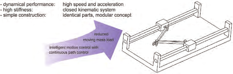
Fig. 2. Benefits of Parallel Kinematics Machines
High dynamical performance is achieved due to the low moved masses. Due to the closed
kinematics the movements of parallel kinematics machines are vibration free for which the
accuracy is improved. Finally, the modular concept allows a cost-effective production of the
mechanical parts.
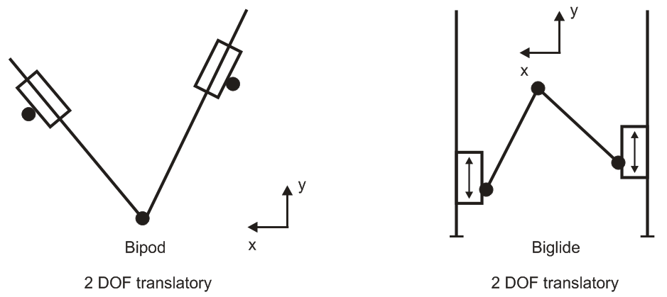
In this chapter, the optimization workspace index is defined as the measure to evaluate the
performance of two degree of freedom Parallel Kinematics Machines. Another important
contribution is the optimal dimensioning of the two degree-of-freedom Parallel Kinematics
Machines of type Bipod and Biglide for the largest workspace using optimization based on
Genetic Algorithms.
Optimal Design of Parallel Kinematics Machines with 2 Degrees of Freedom
297
2. Objective functions used for optimization of machine tools with parallel
kinematics
One of the main influential factors on the performance of a machine tool with parallel
kinematics is its structural configuration. The performance of a machine tool with parallel
kinematics can be evaluated by its kinematic, static and dynamic properties. Optimal design
is one of the most important issues in the development of a parallel machine tool. Two
issues are involved in the optimal design: performance evaluation and dimensional
synthesis. The latter one is one of the most difficult issues in this field. In the optimum
design process, several criteria could be involved for a design purpose, such as workspace,
singularity, dexterity, accuracy, stiffness, and conditioning index.
After its choice, the next step on the machine tool with parallel kinematics design should be
to establish its dimensions. Usually this dimensioning task involves the choice of a set of
parameters that define the mechanical structure of the machine tool. The parameter values
should be chosen in a way to optimize some performance criteria, dependent upon the
foreseen application.
The optimization of machine tools with parallel kinematics can be based on the following
objectives functions:
•
workspace,
•
the overall size of the machine tool,
•
kinematic transmission of forces and velocities,
•
stiffness,
•
acceleration capabilities,
•
dexterity,
•
accuracy,
•
the singular configurations,
•
isotropy.
In the design process we want to determine the design parameters so that the parallel
kinematics machine fulfills a set of constraints. These constraints may be extremely different
but we can mention:
•
workspace requirement,
•
maximum accuracy over the workspace for a given accuracy of the sensors,
•
maximal stiffness of the Parallel Kinematics Machines in some direction,
•
minimum articular forces for a given load,
•
maximum velocities or accelerations for given actuator velocities and accelerations.
Determination of the architecture and size of a mechanism is an important issue in the
mechanism design. Several objectives are contradictory to each other. An optimization with
only one objective runs into unusable solutions for all other objectives. Unfortunately, any
change that improves one performance will usually deteriorate the other. This trade-off
occurs with almost every design and this inevitable generates the problem of design
optimization. Only a multiobjective approach will result in practical solutions for machine
tool applications.
The classical methods of design optimization, such as iterative methods, suffer from
difficulties in dealing with this problem. Firstly, optimization problems can take many
iterations to converge and can be sensitive to numerical problems such as truncation and
round-off error in the calculation. Secondly, most optimization problems depend on initial
298
Parallel Manipulators, Towards New Applications
guesses, and identification of the global minimum is not guaranteed. Therefore, the relation
between the design parameters and objective function is difficult to know, thus making it
hard to obtain the most optimal design parameters of the mechanism. Also, it’s rather
difficult to investigate the relations between performance criteria and link lengths of all
mechanisms. So, it’s important to develop a useful optimization approach that can express
the relations between performance criteria and link lengths.
2.1 Workspace
The workspace of a robot is defined as the set of all end-effector configurations which can be
reached by some choice of joint coordinates. As the reachable locations of an end-effector are
dependent on its orientation, a complete representation of the workspace should be
embedded in a 6-dimensional workspace for which there is no possible graphical
illustration; only subsets of the workspace may therefore be represented.
There are different types of workspaces namely constant orientation workspace, maximal
workspace or reachable workspace, inclusive orientation workspace, total orientation
workspace, and dextrous workspace. The constant orientation workspace is the set of
locations of the moving platform that may be reached when the orientation is fixed. The
maximal workspace or reachable workspace is defined as the set of locations of the end-
effector that may be reached with at least one orientation of the platform. The inclusive
orientation workspace is the set of locations that may be reached with at least one
orientation among a set defined by ranges on the orientation parameters. The set of locations
of the end-effector that may be reached with all the orientations among a set defined by
ranges on the orientations on the orientation parameters constitute the total orientation
workspace. The dextrous workspace is defined as the set of locations for which all
orientations are possible. The dextrous workspace is a special case of the total orientation
workspace, the ranges for the rotation angles (the three angles that define the orientation of
the end-effector) being [0,2π].
In the literature, various methods to determine workspace of a parallel robot have been
proposed using geometric or numerical approaches. Early investigations of robot workspace
were reported by (Gosselin, 1990), (Merlet, 1005), (Kumar & Waldron, 1981), (Tsai and Soni,
1981), (Gupta & Roth, 1982), (Sugimoto & Duffy, 1982), (Gupta, 1986), and (Davidson &
Hunt, 1987). The consideration of joint limits in the study of the robot workspaces was
presented by (Delmas & Bidard, 1995). Other works that have dealt with robot workspace
are reported by (Agrawal, 1990), (Gosselin & Angeles, 1990), (Cecarelli, 1995). (Agrawal,
1991) determined the workspace of in-parallel manipulator system using a different concept
namely, when a point is at its workspace boundary, it does not have a velocity component
along the outward normal to the boundary. Configurations are determined in which the
velocity of the end-effector satisfies this property. (Pernkopf & Husty, 2005) presented an
algorithm to compute the reachable workspace of a spatial Stewart Gough-Platform with
planar base and platform (SGPP) taking into account active and passive joint limits. Stan
(Stan, 2003) presented a genetic algorithm approach for multi-criteria optimization of PKM
(Parallel Kinematics Machines). Most of the numerical methods to determine workspace of
parallel manipulators rest on the discretization of the pose parameters in order to determine
the workspace boundary (Cleary & Arai, 1991), (Ferraresi et al., 1995). In the discretization
approach, the workspace is covered by a regularly arranged grid in either Cartesian or polar
form of nodes. Each node is then examined to see whether it belongs to the workspace. The
accuracy of the boundary depends upon the sampling step that is used to create the grid.
Optimal Design of Parallel Kinematics Machines with 2 Degrees of Freedom
299
The computation time grows exponentially with the sampling step. Hence it puts a limit on
the accuracy. Moreover, problems may occur when the workspace possesses singular
configurations. Other authors proposed to determine the workspace by using optimization
methods (Stan, 2003). Numerical methods for determining the workspace of the parallel
robots have been developed in the recent years. Exact computation of the workspace and its
boundary is of significant importance because of its impact on robot design, robot placement
in an environment, and robot dexterity.
Masory, who used the discretisation method (Masory & Wang, 1995), presented interesting
results for the Stewart-Gough type parallel manipulator:
•
The mechanical limits on the passive joints play an important role on the volume of
the workspace. For ball and socket joints with given rotation ability, the volume of
the workspace is maximal if the main axes of the joints have the same directions as
the links when the robot is in its nominal position.
•
The workspace volume is roughly proportional to the cube of the stroke of the
actuators.
•
The workspace volume is not very sensitive to the layout of the joints on the
platforms, even though it is maximal when the two platforms have the same
dimension (in this case, the robot is in a singular configuration in its nominal
position).
Even though powerful three-dimensional Computer Aided Design and Dynamic Analysis
software packages such as Pro/ENGINEER, IDEAS, ADAMS and Working Model 3-D are
now being used, they cannot provide important visual and realistic workspace information
for the proposed design of a parallel robot. In addition, there is a great need for developing
methodologies and techniques that will allow fast determination of workspace of a parallel
robot. A general numerical evaluation of the workspace can be deduced by formulating a
suitable binary representation of a cross-section in the taskspace. A cross-section can be
obtained with a suitable scan of the computed reachable positions and orientations p, once
the forward kinematic problem has been solved to give p as function of the kinematic input
joint variables q. A binary matrix P ij can be defined in the cross-section plane for a
crosssection of the workspace as follows: if the ( i, j) grid pixel includes a reachable point,
then P ij = 1; otherwise P ij = 0, as shown in Fig. 3. Equations (1)-(4) for determining the
workspace of a robot by discretization method can be found in Ref. (Ottaviano et al., 2002).
Then is computed i and j:
⎡ x + Δ x ⎤
⎡ y + Δ y ⎤
i = ⎢
⎥ j = ⎢
⎥
x
⎣ y ⎦
⎣
⎦
(1)
where i and j are computed as integer numbers. Therefore, the binary mapping for a
workspace cross-section can be given as:
⎧0 if P ∉ W ( H )
P = ⎨
ij
ij
1 if P ∈ W ( H )
⎩
ij
(2)
where W( H) indicates workspace region; ∈stands for “belonging to” and ∉is for “not
belonging t