J J )
det(
C
C T
i
i
J
J
)
i
ji
j
i
j i
j
i
j
i
j
( n& m)
.
.$.
=
C
.
(13)
T
T
T
( n& m& i)
det( JJ )
det( JJ )
det( JJ )
Therefore,
n
n
C
C det(
T
i
i
J J )
2
i
j i
j
( n& m)
' r = '
=
C
.
(14)
j
T
( n& m i
& )
j=1
j=1
det JJ
i
(
)
Dividing both sides by nC to take the mean and noting that,
i
Quantifying and Optimizing Failure Tolerance of a Class of Parallel Manipulators
51
( & )
n
n i
&
C
( n m) C
=
m
C ,
(15)
( n& m i
& )
n
i
Cm
the result follows.
#
This proof leads to the definition of optimal fault tolerant manipulability.
-#+./.0.$/: A manipulator operating about a single point in the workspace is said to be
optimally fault tolerant for a given number of failures i if for all j #{1,2,..., n C }
i
r = c
(16)
i j
where c is a constant.
It is clear from Theorem 1 that if post-fault relative manipulability for certain cases of
failure are higher than the optimal fault tolerant manipulability value, then for other worst
cases of failure, post-fault relative manipulabilities are extremely low. This has precisely
been the motivation for developing optimally fault tolerant manipulators and the above
definition arises as a direct consequence.
1$%$223%4'5)' A manipulator characterized by J #" and operating about a single point in the
workspace is optimally fault tolerant to i faults if
( n i
& ) C
r =
m
(17)
i
j
n Cm
for all j #{1,2,..., n C } .
i
*%$$+, Equation (16) defines manipulators with optimal fault tolerant manipulability for i
faults. By Theorem 1, if each r is constant, c is given by equation (1)
i
j
#
Roberts and Maciejewski (Roberts & Maciejewski, 1996) present a singular value
decomposition approach to identify fault tolerant configurations for serial manipulators and
describes a rigorous method to determine whether a given nominal configuration possesses
optimal fault tolerant manipulability. The above theorem states a formulation which directly
gives the value of optimal manipulability under a given number of failures, for any
manipulator with a given number of actuators. In fact, the theorem proves that irrespective
of the operating configuration, all manipulators having the same number of actuators, have
the same value of optimal manipulability under a given number of failures. This new idea
plays a key role in the design of fault tolerant serial manipulators. The following example
illustrates this point.
Suppose a fault tolerant serial manipulator is to be designed such that it has 3 degrees of
freedom ( m = 3) and it is desired to have an optimal fault tolerant manipulability of 0.5
( r = 0.5) under a single-actuator failure ( i = 1) . This implies that the manipulator operating
i
j
in the nominal configuration, should be able to sustain the failure of any actuator and retain
half of its manipulability. Substituting all known values in equation (1), we get n = 4 . This
means that the manipulator has to have 4 actuators in order to have optimal fault tolerant
manipulability for single failure.
52
Parallel Manipulators, Towards New Applications
Another implication of this theorem is significant in terms of understanding post-fault
behavior of any manipulator. From equation (14), it is clear that if the value of r is quite
i
j
close to ( n& m) C
for some j then the reduction in manipulability is far more pronounced if
( n& m& i )
a possible failure combination corresponding to some other j were to occur. Taking this
into account, it is possible to assemble the actuators in such a way that actuators which are
more likely to fail (for example, actuators with actuators that are more likely to have
manufacturing defects) correspond to those j which give
( n& i) C
r >
m .
i j
n Cm
This idea has a greater impact on the design of parallel manipulators. While actuator failures
may cause a serial manipulator to stop functioning, actuator failures have a comparatively
smaller effect on redundant parallel manipulators because they can retain kinematic
stability. Therefore, the two consequences that can be applied to the design of serial
manipulators are applicable to parallel manipulators as well.
The most significant area of investigation where the above results influence parallel
manipulator design is the choice of geometry. This area will be explored in the Section 5.
3.3 Examples
Some specific examples provide more insight to understanding this concept of optimal fault
tolerant manipulability.
Number of Number of Sum of all Optimal Fault
Nominal
Failures
possible
Tolerant
Actuators
i
2
r
n
Manipulability
i
j
7
1
1
0.377
8
1
2
0.500
8
2
2
0.189
9
1
3
0.577
9
2
3
0.288
9
3
3
0.109
Table 1. Optimal Fault-tolerant manipulability of 6-dof redundant manipulators
It is clear from Table 1 that as the number of failures increases, the optimal fault tolerant
manipulability decreases drastically, regardless of the geometry. Consider the example of
any 8-actuator manipulator suffering from 2 simultaneous failures. The sum of squares of
relative manipulabilities is 2 for 28 failure possibilities. This means that if some post-fault
relative manipulabilities are more than the optimal fault tolerant manipulability (0.189),
then the worst case values are far less than 0.189. Therefore, irrespective of the geometry of
the 8-actuator manipulator, for worst cases of failure the relative manipulabilities will have
negligible values. Hence, it is important to design manipulators that are optimally fault
tolerant to a given number of failures.
Quantifying and Optimizing Failure Tolerance of a Class of Parallel Manipulators
53
Table 1 also provides another important inference which is significant from the design
perspective. Any redundant manipulator gives very low optimal fault tolerant
manipulability values for more than one failures, and these values decrease drastically with
number of failures. For example, for two failures in an octopod the optimal fault tolerant
manipulability is 0.189 and, for two and three failures in a nanopod the optimal fault
tolerant manipulabilities are 0.288 and 0.109 respectively. This means that under the
hypothesis of equal probability of failure for each actuator, it is not practical to design
manipulators optimally fault tolerant to more than one fault.
4. Symmetric orthogonal Gough Stewart platforms
4.1 Gough Stewart platforms
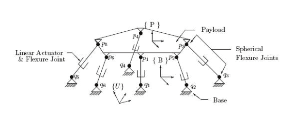
A Gough-Stewart Platform (GSP) is a parallel manipulator consisting of a base, a moving
platform (or payload) and struts. The length of struts is controlled by actuators. The struts
have spherical joints at the payload end and U joints at the base. To provide six degrees of
freedom, six struts are commonly used. Figure 1 is a diagrammatic representation of a GSP.
Payload attachment points and base attachment points are represented by p and q
i
i
( i #
,6}
{1,2,3,4,5
) respectively.
Fig. 1. Gough-Stewart Platform
OGSPs are a special class of GSPs that provide kinematic and dynamic decoupled control.
Therefore, OGSPs are being widely used in commercial, military and space applications.
Scientists at Northrop Grumman Space Technologies (NGST) are currently experimenting
with an 8-strut OGSP. More recent applications of OGSPs include laser tracking and
pointing, ultra-precise manipulation (McInroy & Jafari, 2006) and robotic surgery (Wapler et
al., 2003). The very nature of these applications makes maintenance or repair of
manipulators very difficult. Moreover, a single failure may compromise the fulfilment of
objective or cause costly downtime. As a consequence, it is desirable to design OGSPs which
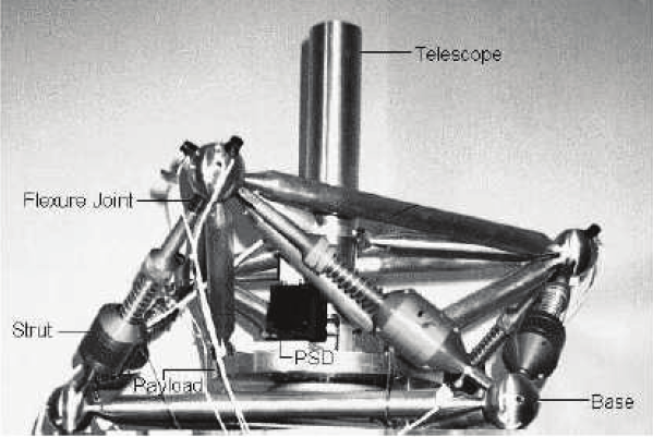
can sustain failures, while retaining an acceptable level of manipulability. Figure 2 shows
one of the flexure jointed hexapods at the University of Wyoming. It has a mutually
orthogonal geometry.
54
Parallel Manipulators, Towards New Applications
Fig. 2. A Flexure Jointed Hexapod at the University of Wyoming
Recent research has shown that symmetric groups of struts can be used to generate OGSPs
having desired properties at their home position (McInroy & Jafari, 2006) and several new
results have been obtained.
The following part of this section recapitulates important results from (McInroy & Jafari,
2006).
4.2 Kinematics of symmetric OGSPs
The inverse Jacobian, M , of a GSP maps the generalized velocity of the payload to the
corresponding joint velocities of each strut (!!" = MV ). It has the form:
"
"
T
T
( u
v )
1
1
*
+
M = * %
% +
(18)
"
"
T
T
* u
v +
, l
l -
" "
"
"
"
"
"
where
3
u , v #R , v = p $ u . u is the unit vector along strut i and
3
p #R is the moving
i
i
i
i
i
i
i
platform attachment point of strut i . Please refer to Figure 1. Note that, even though M is
called the inverse Jacobian to comply with the robotics standard, its computation does not
require inversion, thus it is well defined for all GSP.
-#+./.0.$/6, Let M # M (R) . Write
l$6
=
T
T
M
U
(
V )
,
-
Quantifying and Optimizing Failure Tolerance of a Class of Parallel Manipulators
55
where U , V # M (R) . We say M # GSP, M is a Gough-Stewart Platform, if:
3$ l
/
diag( U TU ) = [11 1]
#
/
diag( U TV ) = 0
We say M is a Weighted Orthogonal Gough-Stewart Platform, M # w-OGSP, if M # GSP
and:
/
M T KM is a diagonal matrix for a diagonal K .
Where K = I these matrices become the Orthogonal Gough-Stewart Platforms.
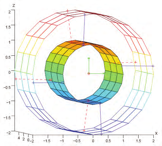
Fig. 3. [4 4] cylindrical OGSP with optimal fault tolerant manipulability
(McInroy & Jafari, 2006) develops properties and designs of symmetrical weighted OGSPs.
Struts that are geometrically symmetrical are treated together, so the entire OGSP is
decomposed into m different groups, with the th
i group having n struts. Then
i
"
n = 0 n n ...
T
n
1
2
m 1
is a vector of positive integers describing the number of struts in each group. The total
" "
number of struts in the GSP is then
m
l = ' n . Let
3
u , v #R correspond to the th
i strut in
j 1
=
j
ij
ij
" "
" "
"
" "
" "
"
group j . Let U = [ u u # u u # u ] and V = [ v v # v v # v ] . A GSP can then be found 11
21
n 1
12
1
n m
m
11
21
n 1
12
1
m
m
n
for these struts by letting M = [ T
T
U
V ] .
56
Parallel Manipulators, Towards New Applications
Following is the summary of results in (McInroy & Jafari, 2006).
*%$7$6.0.$/'8) Conditions (a) and (b) in the GSP definition are satisfied if
( S C )
i
2 j 3 ij
*
+
"
"
"
"
u = * S S + , v = x v . y v
(19)
ij
2
3
ij
ij x
ij
y
ij
ij
ij
ij
*
+
* C
+
,
i
2 j
-
where S = sin x , C = cos x , 4 ,3 , x , y #R , and
x
x
ij
ij
ij
ij
S
( C C )
(
)
3 ij
i
2 j 3 ij
*
+
"
*
+ "
v = * C
&
+ , v = * C S +.
(20)
x
3
y
ij
ij
ij
i
2 j 3 ij
*
+
*
+
* 0
,
+
* & S +
-
,
i
2 j -
Conversely, if M # GSP, then M may be represented by a parameterization given by (19)
and (20).
!"#$%#&'9) Let all groups contain more than two struts, i.e. min n
. Then M # w-OGSP
j
> 2
j
if
/ The same angle, 4 , is used for all struts in group j , i.e. 4 = 4 ,
j
ij
j
"
/ The same x component of v , x , is used for all struts in group j , i.e. x = x ,
j
ij
j
"
/ The same y component of v , y , is used for all struts in group j , i.e. y = y ,
j
ij
j
/ The same k , k , is used for all struts in group j , i.e. k = k ,
j
ij
j
5 &
/
2 i
(
1)
Struts in a group are rotated about the z-axis equal amounts, i.e. 3 = 3 .
,
ij