In order to proceed with the discussion we have to define two terms. A wave front is the surface of constant phase. In a plane wave these are planes and in a spherical wave these are spheres. A ray travels perpendicular to the fronts.
Huygens postulated that as a wave propagates through a medium each point on the advancing wavefront acts as a new point source of the wave. This is correct physics for the water waves but not for light waves. However the Helmholtz equation for diffraction of EM waves gives a solution identical to that give by Huygens' principle.
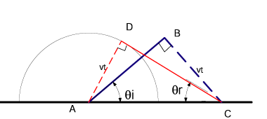
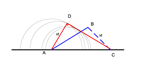
Look at the figure which shows a wavefront AB coming to a surface and is reflected creating the front CD. The point A hits the surface first. The point B hits a time vt later. During that time a spherical wave is emitted from A and travels a distance vt . In fact this happens for every point along the wavefront. The next figure attempts to show how a number of waves line up along the line DC and that this is perpendicular to the line AD.
From this we see that
 and
and
 so
θi
=
θr
so
θi
=
θr
For refraction a similar thing happens. See figure (geometric optics / Huygens refraction.vsd )
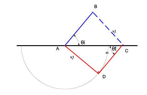
In this case the velocities are different in the two media and so one obtains:
 and
and
 which
then can be rearranged
which
then can be rearranged
 or
rearranging some more
or
rearranging some more
 or
or
 finally
nt
sin
θt
=
ni
sin
θiwhich
is Snell's law. Now note that normally one uses rays, in which case the angles
are measured w.r.t. the normal to the surface.
finally
nt
sin
θt
=
ni
sin
θiwhich
is Snell's law. Now note that normally one uses rays, in which case the angles
are measured w.r.t. the normal to the surface.
Fermat postulated that rays of light follow the path that takes the least time. This is a very profound idea! There is something very deep in it. It also gives the experimentally observed results! Lets apply it to reflection and see what results:
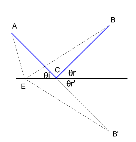
We want to find the length (which is the same as time times the speed) AEB. To do this we construct a fake point B' which is on the other side of the surface the same perpendicular distance from the surface such that the line BB' is a perpendicular to the surface. Then clearly the length AEB equals the length AEB'. So which point on the surface gives the shortest path to B, the one that gives the shortest path to B' and that clearly lies on the straight line AB'. I have labeled this point C.
Now clearly θr = θr′ and also θr′ = θi so we get θr = θi
Now lets apply Fermat's principle to refraction. Look at the next figure:
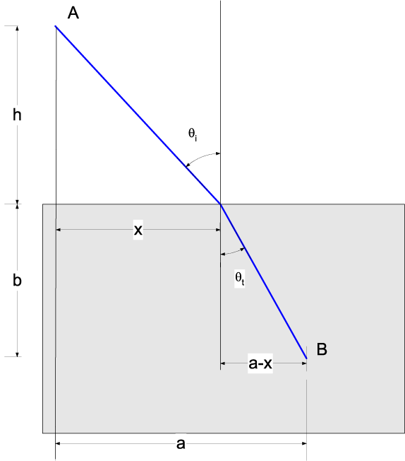
We want the shortest time from A to B. Clearly that is
To find the minimum we want to solve for
x
such that
Thus
which
is obviously
or
Snell's law
nt
sin
θt
=
ni
sin
θi
If light travels via many different media then the time is
or
we can rewrite this as
 The
quantity
The
quantity
 is the optical path length
(
OPL
)
.
For a continuously varying medium then the summation becomes (for light
traveling from
S
to
P
)
OPL
=
∫SPn
(
s
)
ⅆ
s
Fermat's
principle could be restated that we minimize the
OPL
In fact this is inadequate, for example one can construct an example where the
optical path length is not the minimum.(See for example figure 4.37 in the
book "Optics" by Hecht (Fourth Edition).The correct statement of Fermat's
principle is that there is a stationary point in the optical path length. (Ie.
its derivative is zero).
is the optical path length
(
OPL
)
.
For a continuously varying medium then the summation becomes (for light
traveling from
S
to
P
)
OPL
=
∫SPn
(
s
)
ⅆ
s
Fermat's
principle could be restated that we minimize the
OPL
In fact this is inadequate, for example one can construct an example where the
optical path length is not the minimum.(See for example figure 4.37 in the
book "Optics" by Hecht (Fourth Edition).The correct statement of Fermat's
principle is that there is a stationary point in the optical path length. (Ie.
its derivative is zero).
We want to understand with Electromagnetism what happens at a surface. From
Maxwell's equations we can understand what happens to the components of the
 and
and
 fields: First lets look at the
field using Gauss' law. Recall
fields: First lets look at the
field using Gauss' law. Recall
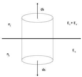
Consider
the diagram, the field on the incident side is
 .
On the transmission side, the field is
.
We can collapse the cylinder down so that it is a pancake with an infinitely
small height. When we do this there are no field lines through the side of the
cylinder. Thus there is only a flux through the top and the bottom of the
cylinder and we have;
I have set
∫
ρ
ⅆ
V
=
0
since we will only consider cases without free charges. So we have
εiEi
⊥
+
εiEr
⊥
=
εtEt
⊥
if
is a unit vector normal to the surface this can be written
.
On the transmission side, the field is
.
We can collapse the cylinder down so that it is a pancake with an infinitely
small height. When we do this there are no field lines through the side of the
cylinder. Thus there is only a flux through the top and the bottom of the
cylinder and we have;
I have set
∫
ρ
ⅆ
V
=
0
since we will only consider cases without free charges. So we have
εiEi
⊥
+
εiEr
⊥
=
εtEt
⊥
if
is a unit vector normal to the surface this can be written
Similarly Gauss' law of Magnetism
gives
Bi
⊥
+
Br
⊥
=
Bt
⊥
or

Amperes law can also be applied to an interface.Then
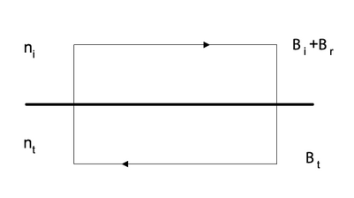
 (note that in this case
 is perpendicular to the page)
Now we will not consider cases with surface currents. Also we can shrink the
vertical ends of the loop so that the area of the box is 0 so that
 .
Thus we get at a
surface
.
Thus we get at a
surface or
or

Similarly we can use Faraday's law
 and play the same game with the edges to get
Ei
∥
+
Er
∥
=
Et
∥
or
and play the same game with the edges to get
Ei
∥
+
Er
∥
=
Et
∥
or
 (notice
ε
does not appear)
(notice
ε
does not appear)
In summary we have derived what happens to the
 and
and
 fields at the interface between two
media:
fields at the interface between two
media:


Consider an electromagnetic wave impinging upon an interface:
Where
describes the incoming wave,
the reflected wave, and
the transmitted wave. At the interface (ie. at points where the vector
points to the plane of the interface), all the waves must be in phase with
each other. This means that the frequencies must all be equal and there can be
no arbitrary phase between the waves. The net result of this is that we must
have (for an interface passing through the origin):
from which we get
ki
sin
θi
=
kr
sin
θr
.
It is important to note now that we are doing this at the interface. We have
chosen a coordinate system so that the interface is at
y
=
0
and contains the origin. This implies that the vector
is lying in the plane of the interface at the point where we say that the
above is true.
Finally, since the incident and reflected waves are in the same medium we must
have
ki
=
kr
and thus
θi
=
θrAlso,
we get that
all line in a plane (because
 defines a plane). We also have
and
following the same arguments find that
all line in a plane and that
ki
sin
θi
=
kt
sin
θt
.
Now
we know that
ωi
=
ωt
so we can multiply both sides by
c
/
ωi
and get
ni
sin
θi
=
nt
sin
θt
defines a plane). We also have
and
following the same arguments find that
all line in a plane and that
ki
sin
θi
=
kt
sin
θt
.
Now
we know that
ωi
=
ωt
so we can multiply both sides by
c
/
ωi
and get
ni
sin
θi
=
nt
sin
θt
At the interface, which we will set to
y
=
0
for convenience (you can always switch back to any coordinate system
afterwards. It is good practice to choose the coordinate system that makes
your problem easy)
 now this must be true for all