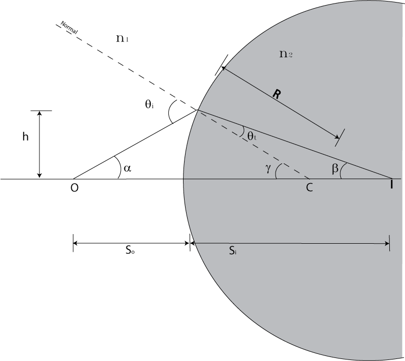
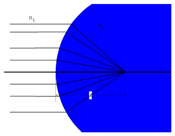
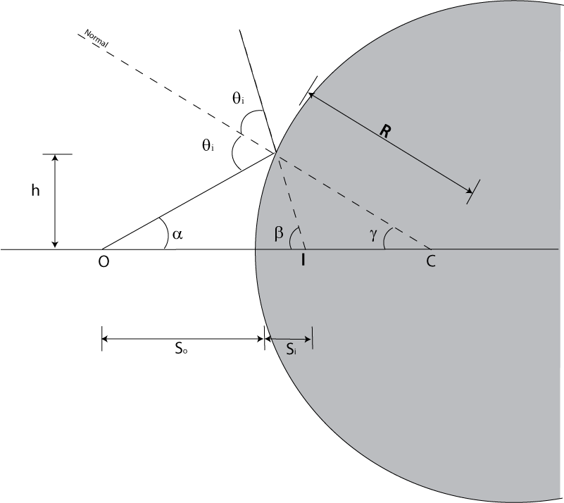
Look at the figure showing refraction at a sphere.In this figure:
C is the center of curvature of the spherical surface
R is the radius of curvature
O is the position of the Object
I is the position of the Image
So is the distance of the object from the surface along the optical axis
Si is the distance from the surface to the Image
n1 < n 2
There is a ray that strikes the surface at height h. In general rays hitting
the surface at different points will be bent to different points along the
optical axis. However for small angles we will show they all converge at the
same point.So lets use the small angle
approximation

 Now from trigonometry we can see that:
θi
=
α
+
γ
γ
=
θt
+
β
or
θt
=
γ
−
β
now Snell's law says
n1
sin
θi
=
n2
sin
θt
or
n1θi
≈
n2θt
n1
(
α
+
γ
)
=
n2
(
γ
−
β
)
γ
(
n2
−
n1
)
=
n2β
+
n1α
Now from trigonometry we can see that:
θi
=
α
+
γ
γ
=
θt
+
β
or
θt
=
γ
−
β
now Snell's law says
n1
sin
θi
=
n2
sin
θt
or
n1θi
≈
n2θt
n1
(
α
+
γ
)
=
n2
(
γ
−
β
)
γ
(
n2
−
n1
)
=
n2β
+
n1α
 Now all the
h
's
cancel so there is no dependence on point on surface. That is:
Now all the
h
's
cancel so there is no dependence on point on surface. That is:
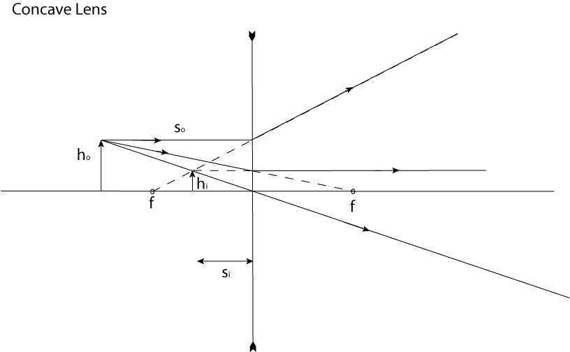
 Now lets consider the case of a concave surface. The picture is
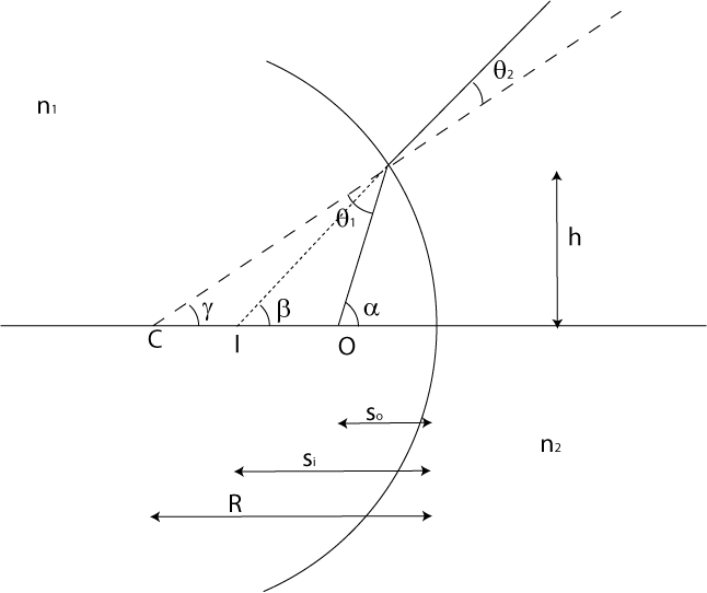
Again
we use the small angle approximation and thus we have
n1θ1
=
n2θ2
In this case we also see that
α
=
θ1
+
γ
and
β
=
θ2
+
γ
so we can write
n1
(
α
−
γ
)
=
n2
(
β
−
γ
)
or
 or
or

However we can make the equation identical to the previous one if we adopt the following sign convention:
so is positive to the left of the interface
si is positive to the right of the interface
R is positive when the center of the sphere is to the right of the interface
Then the equation becomes as before

In this case note that the image is imaginary (whereas in the first case it was real). Note that the actual rays pass through a real image.
The focal point is the object point which causes the image to occur at infinity.
That
is all the rays end up traveling parallel to each other. In this case
si
goes
to
∞
so
 becomes
 or
or
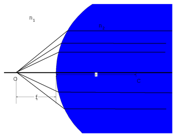
Now we can find a focal point to the right of the of the surface by considering parallel rays coming in from the left.
Then
we get
 But we do have to expand our sign conventionfor light
incident from the left
But we do have to expand our sign conventionfor light
incident from the left
so is positive to the left of the interface
si is positive to the right of the interface
R is positive when the center of the sphere is to the right of the interface
fo is positive to the left of the interface
fi is positive to the right of the interface
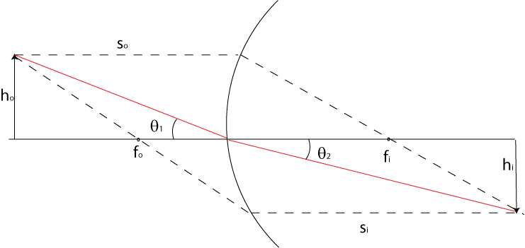
With the definition of focal points, we also have a natural way to graphically solve optical problems. Any ray drawn horizontally from the left side of the interface will pass through the focal point on the right. Any ray going through the focal point on the left will go horizontally on the right. The following figure illustrates this.
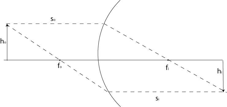
The magnification of the image is the ratio of the heights ho to hi.
Since we are using the small angle approximation, we have Snell's law
n1θ1
=
n2θ2
which can be rewritten
 So we write that the magnification is
 The negative sign is introduced to capture the fact that the image is
inverted. It is worth pointing out that in our diagram above, the image is
real, because the actual light rays pass through it.
The negative sign is introduced to capture the fact that the image is
inverted. It is worth pointing out that in our diagram above, the image is
real, because the actual light rays pass through it.
Now we can turn to the case of lenses. A lens can be considered the combination of two spherical interfaces. To solve an optical problem using multiple interfaces or lenses, one considers each one by one. For example one finds the image created by the first surface and then uses it as the object of the second surface.
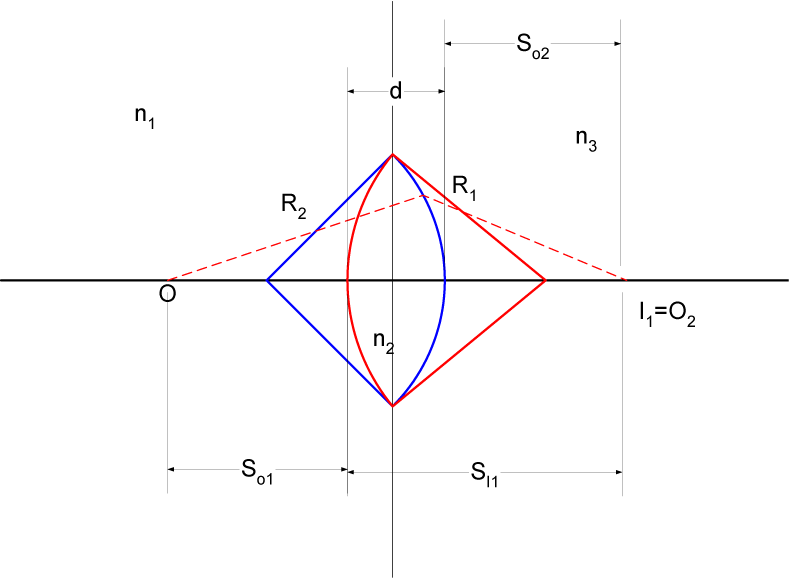
Consider
a lens of thickness
d
as shown in the drawing. At interface 1 (coloured red in the drawing) we
have
 For
surface 2 (coloured blue) the image of the the first surface becomes the object
of the second. Note the sign of
so2
is negative so that
so2
=
d
−
si1Thus
becomes
Now
add the equations
For
surface 2 (coloured blue) the image of the the first surface becomes the object
of the second. Note the sign of
so2
is negative so that
so2
=
d
−
si1Thus
becomes
Now
add the equations
Now
we take the thin lens case,that is
d
→
0
 That
equation would work for making prescription swim goggles for example, however
most of the time
n1
=
n3
(namely air for eyeglasses). So making that the case we get
which
in the case of air (n=1) is
That
equation would work for making prescription swim goggles for example, however
most of the time
n1
=
n3
(namely air for eyeglasses). So making that the case we get
which
in the case of air (n=1) is
 That
is The lensmaker's formula(where
nl
is the index of refraction of the lens material)Now we can find
the foci
That
is The lensmaker's formula(where
nl
is the index of refraction of the lens material)Now we can find
the foci

 Which
we see from the lensmaker's formula must be the same so lets drop the
subscripts:
Which
we see from the lensmaker's formula must be the same so lets drop the
subscripts:
 and
and
 which
is the Gaussian Lens Formula
which
is the Gaussian Lens Formula
A convex lens will have a positive focal length f .
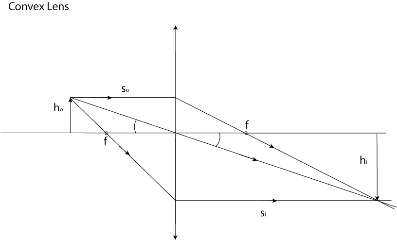
We can use the same equation as before for the magnification,
but
now note that
n1
=
n2
so the equation becomes
 You
can examine the figure above to verify that this is true.
You
can examine the figure above to verify that this is true.
We can also consider a concave lens which has a negative focal length. Notice that in this case the image is upright and virtual. Notice that in this case si is negative.
Notice that in Mirrors we get a virtual image to the right of the surface. Thus for mirrors we say that si is positive to the left of the mirror. This allows to retain correspondence between si being negative and an image being virtual.
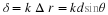
Again we use the small angle approximation. By inspection of the figure we see
that
2
θi
=
α
+
β
and
θi
=
α
+
γ
.
Now
we multiply the second equation by two and subtract the first equation from it
and we get:
2
α
+
2
γ
−
α
−
β
=
0
or
α
−
β
=
−
2
γ
.
Using
the small angle approximation we see that this is
where
I have used the fact that
si
is negative to the right of the mirror. So I can write the mirror equation as
 or
or
 where
for a mirror
1
/
f
=
−
2
/
R
where
for a mirror
1
/
f
=
−
2
/
R
First a little nomenclature. Optometrists (and opthamologists) use the
dioptric power measured in diopters. A diopter is
1
/
f
where f is measured in meters. The focal length of lenses in contact is
or using dioptric power
D
=
D1
+
D2
A "normal" eye will focus an object at infinity onto the r