0.6125
0.5 Nrated
1
55.15
0.761
62.34
13.04
(5)
0.75
0.5 Nrated
1
60.175
0.8312
65.31
8.53
(6)
1
0.5 Nrated
1
63.54
0.8722
68.15
7.26
Table 3. Summary of the results of the two controllers
Swarm Intelligence Based Controller for
Electric Machines and Hybrid Electric Vehicles Applications
173
In practical system, the flux level based on PSO at different operating points (torque and
speed) is calculated and stored in a look up table (LUT). The use of look up table will enable
the system to work in real time without any delay that might be needed to calculate the
optimal point. The proposed controller would receive the operating point (torque and
speed) and get the optimum flux (λoptimal) from the look up table. It will generate the
required reference current. It is noticed that, the efficiency with the FOC based on PSO
method is higher than the efficiency with the FOC method only.
2.6 Experimental results
To verify the validity of the proposed control scheme, a laboratory prototype is built and
tested [Hegazy, 2006; Amin et al., 2006; Amin et al., 2009]. The basic elements of the
proposed experimental scheme are shown in Fig. 8 and Fig. 9. The experimental results of
the motor are achieved by coupling the motor to an eddy current dynamometer. The
experimental results are achieved using two control methods:
•
Field-Oriented Control [FOC], and
•
Field-Oriented Control [FOC] based on PSO.
The reference and the actual motor currents are fed to the hysteresis current controller. The
switching pattern of the two-level four-switch inverter [FSI] is generated according to the
difference between the reference currents and the load currents. Figure 10 shows the
experimental results of the motor with FOC at case (1), where the motor is loaded by TL =
0.25 PU. Figure 11 shows the experimental result of the motor with FOC based on PSO at
case (1). The cases are summarized in Table 4.
Two dc-supply
Switching
Pattern
Inverter
4
IN
ω
isqs
Ia_ref
ref
T*e
i
+
PI
Indirect
dq-->ab
a
T
Iaact
Field-Oriented
-
E
transfor-
Hystersis
is
R
φ*
ds
me
current
I
-
b_ref
FA
controller
Rotor
ib
Ibact
PSO
CE
ωactual
Shaft
encoder
ωactual
M/c
paramaters
Tl Nr
Fig. 8. Block diagram of the proposed experimental scheme [Hegazy, 2006; Amin et al., 2009]
FOC
FOC with PSO
Cases
Improvement
λ
Power
η
λ
Power
η
(%)
(PU
Input (W)
(%)
(PU
Input (W)
(%)
(1)
1 235
32.3
0.636
169
44.92 39.07
(2)
1 323
35.2
0.690
243
47.06 33.69
Table 4. The summary of the two-cases
174
Electric Machines and Drives
D
D
Rs
Rs
S
D
1
1
S
D
2
2
Cs
C
E
G
G2
s
dc
1
S
S
iqs
D
main
E
rotor
dc
D
S
R
2
s
S
R
4
s
D3
D4
S
G2
C
G4
C
S
s
s
ids aux
Fig. 9. The power circuit of Four Switch Inverter [FSI]
(a)
(b)
Swarm Intelligence Based Controller for
Electric Machines and Hybrid Electric Vehicles Applications
175
(c)
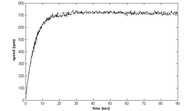
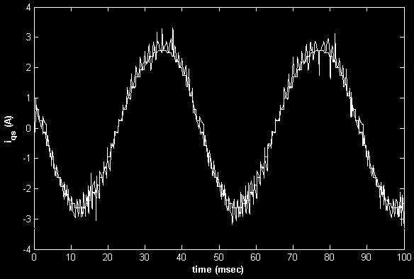
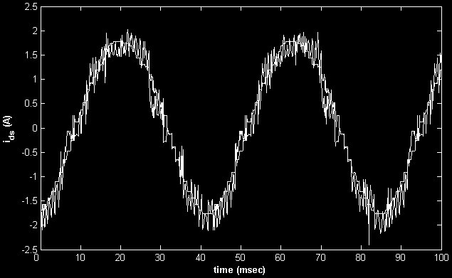
Fig. 10. Experimental results of FOC method; the reference and actual speed, (b) the
reference and actual current in q-axis, (c) The reference and actual current in d-axis
(a)
(b)
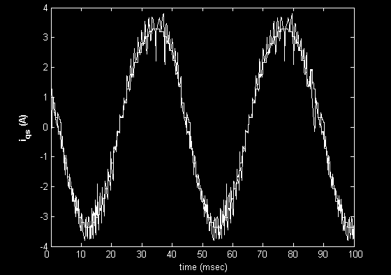
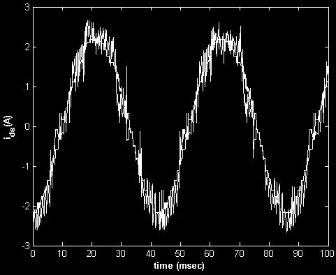
Fig. 11. Experimental results of FOC method based on PSO. (a) The reference and actual
current in q-axis, the reference and actual current in d-axis
176
Electric Machines and Drives
Finally, these results demonstrate that, the FOC based on PSO method saves more energy
than conventional FOC method. Thus, the efficiency with PSO is improved than it's at FOC.
3. Maximum efficiency and minimum operating cost of induction motors
This section presents another application of PSO for losses and operating cost minimization
control in the induction motor drives. Two control strategies for induction motor speed
control are proposed. Those two strategies are based on PSO and called Maximum Efficiency
Strategy and Minimum Operating Cost Strategy [A. Hamid et al. 2006]. The proposed
technique is based on the principle that the flux level in the machine can be adjusted to give
the minimum amount of losses and minimum operating cost for a given value of speed and
load torque. The main advantages of the proposed technique are; its simple structure. It is a
straightforward maximization of induction motor efficiency and its operating cost for a given
load torque. As was demonstrated, PSO is efficient in finding the optimum operating
machine's flux level. The optimum flux level is a function of the machine operating point.
The main induction motor losses are usually split into five components: stator copper losses,
rotor copper losses, iron losses, mechanical losses, and stray losses [Kioskeridis & Margaris,
1996].
The efficiency that decreases with increasing losses can be improved by minimizing the losses.
Copper losses reduce with decreasing the stator and the rotor currents, while the core losses
essentially increase with increasing air-gap flux density. A study of the copper and core losses
components reveals that their trends conflict. When the core losses increase, the copper losses
tends to decrease. However, for a given load torque, there is an air-gap flux density at which
the total losses is minimized. Hence, electrical losses minimization process ultimately comes
down to the selection of the appropriate air-gap flux density of operation. Since the air-gap
flux density must be variable when the load is changing, control schemes in which the (rotor,
air-gap) flux linkage is constant will yield sub-optimal efficiency operation especially when the
load is light. Then to improve the motor efficiency, the flux must be reduced when it operates
under light load conditions by obtaining a balance between copper and iron losses.
The challenge to engineers, however, is to be able to predict the appropriate flux values at
any operating points over the complete torque and speed range which will minimize the
machines losses, hence maximizing the efficiency. In general, there are three different
approaches to improve the induction motor efficiency especially under light-load.
a. Losses Model Controller (LMC)
This controller depends on a motor losses model to compute the optimum flux analytically.
The main advantage of this approach is its simplicity and it does not require extra hardware.
In addition, it provides smooth and fast adaptation of the flux, and may offer optimal
performance during transient operation. However, the main problem of this approach is
that it requires the exact values of machine parameters. These parameters include the core
losses and the main inductance flux saturation, which are unknown to the users and change
considerably with temperature, saturation, and skin effect. In addition, these parameters
may vary due to changes in the operating conditions. However, with continuing
improvement of evolutionary parameter determination algorithms, the disadvantages of
motor parameters dependency are slowly disappearing.
b. Search Controller (SC)
This controller measures the input power of the machine drive regularly at fixed time
intervals and searches for the flux value, which results in minimum power input for given
Swarm Intelligence Based Controller for
Electric Machines and Hybrid Electric Vehicles Applications
177
values of speed and load torque. This particular method does not demand knowledge of the
machine parameters and the search procedure is simple to implement.
However, some disadvantages appear in practice, such as continuous disturbances in the
torque, slow adaptation (7sec.), difficulties in tuning the algorithm for a given application,
and the need for precise load information. In addition, the precision of the measurements
may be poor due to signal noise and disturbances. This in turn may cause the SC method to
give undesirable control performance. Moreover, nominal flux is applied in transient state
and is tuned after the system reaches steady state to an optimal value by numerous
increments, thus lengthening the optimization process. Therefore, the SC technique may be
slow in obtaining the optimal point. In addition, in real systems, it may not reach a steady
state and so cause oscillations in the air gap flux that result in undesirable torque
disturbances. For these reasons, this is not a good method in industrial drives.
c. Look Up Table Scheme
It gives the optimal flux level at different operating points. This table, however, requires
costly and time-consuming prior measurements for each motor. In this section, a new
control strategy uses the loss model controller based on PSO is proposed. This strategy is
simple in structure and has the straightforward goal of maximizing the efficiency for a given
load torque. The resulting induction motor efficiency is reasonably close to optimal. It is
well known that the presence of uncertainties, the rotor resistance, for instance makes the
result no more optimal. Digital computer simulation results are obtained to demonstrate the
effectiveness of the proposed method.
3.1 Definition of operating strategies
The following definitions are useful in subsequent analyses. Referring to the analysis of the
induction motor presented in [A. Hamid et al. 2006], the per-unit frequency is
ω
ω + ω
e
s
r
a =
=
(39)
ω
ω
b
b
The slip is defined by
ω
ω
s
s
s =
=
(40)
ω
ω + ω
b
s
r
The rotor current is given by
'
φ m
I =
(41)
r
2
'
⎛
⎞
2
⎜ r
'
r ⎟ +
⎜
⎟
Xlr
sa
⎝
⎠
The electromagnetic torque is given by
'
⎛
⎞
⎜ r ⎟
r
⎜⎜ sa ⎟⎟
⎝
⎠
(42)
=
e
T
2
φ2
'
m
⎛
⎞
2
⎜
⎟
'
rr +
⎜⎜ sa ⎟ X lr
⎟
⎝
⎠
178
Electric Machines and Drives
The stator current is related to the air gap flux and the electromagnetic torque as:
2
2
3
5
⎛
⎞
T
I = ⎜ S φ
e
+
+
⎟ +
s
1 m
S 2φ
S 2φ
CL
(43)
m
m
⎝
⎠
φ2 m
Where
x' lr
C = + ×
L
1 2 xm
The air gap flux is related to the electromagnetic torque as:
2
'
⎛
⎞
sa ⎜ r
2
⎟
(44)
r
'
φ =
+
m
⎜
⎟
e
T
'
xlr
⎜ sa
r
⎟
r
⎝
⎠
The efficiency is defined as the output power divided by the electric power supplied to the
stator (inverter losses are included):
P
out
(
Efficiency η ) =
(45)
in
P
3.1.1 Maximum efficiency strategy
In MES (Maximum Efficiency Strategy), the slip frequency is adjusted so that the efficiency
of the induction motor drive system is maximized [A. Hamid et al. 2006].
The induction motor losses are the following:
1. Copper losses: these are due to flow of the electric current through the stator and rotor
windings and are given by:
2
2
'
'
=
+
cu
P
s
r I
(46)
s
rrIr
2. Iron losses: these are the losses due to eddy current and hysteresis, given by
2
2
P
= K (
2
+ S ) 2
1
a ϕ + K (1 +
ϕ
core
e
h
S) a
(47)
m
m
3. Stray losses: these arise on the copper and iron of the motor and are given by:
2
2 '
=
cu
P
Cstr ω
(48)
r I r
4. Mechanical losses: these are due to the friction of the machine rotor with the bearings
and are given by:
2
=
+
fw
P
C fw ω (49)
r
5. Inverter losses: The approximate inverter loss as a function of stator current is given by:
Swarm Intelligence Based Controller for
Electric Machines and Hybrid Electric Vehicles Applications
179
2
=
+
(50)
inv
P
K 1 invis K 2 invis
Where: K1inv, K2inv are coefficients determined by the electrical characteristics of a switching
element where: K1inv= 3.1307e-005, K2inv=0.0250.
The total power losses are expressed by:
2
⎡
2
'
'
P
P
P
P
P
r
P
⎤
=
+
+
+
+
=
+
+
losses
cu
core
s
fw
inv
⎢ s I s rr I r ⎥
⎣
⎦
⎡ K +
ϕ ⎤ ⎡
+
+
ϕ ⎤ ⎡
⎤
+
(51)
e
⎢ (
2
1 S )
2
2
a
Kh (1 S)
2
2
2 '
a
C
⎣
⎥⎦ ⎢⎣
⎥ ⎢ str ω
⎦
I
m
m
r
r ⎥
⎣
⎦