+
+
( F
F
F
F
) * V
g
roll
AD
acc
P
=
(61)
load
η GB
F = M . g. sin(α )
g
(62)
F
= M . g. f .cos(α)
roll
r
(63)
2
F
= .
0 5 ρ . C . A . V
AD
a D F
(64)
dV
F
= M .
acc
dt
(65)
V = ω . r
w w
(66)
The total electric power required from sources can be expressed as:
Pload
P
=
(67)
req
η η
.
η
.
m Inv Conv
The parameters of the vehicle are given in Table 6. The analysis of FCHEV is performed
with two standard driving cycles:
1. The Federal Test Procedure (FTP75) Urban;
2. The New European Driving Cycle (NEDC)
Suppose that the efficiencies of the motor (ηm), inverter (ηInv), and MIPEC (ηConv= ηB= η B/B)
are 0.90, 0.94 and 0.95, respectively.
M
Vehicle mass (kg)
1450
Af
Front Area (m2)
2.13
Radius of the
fr
Rolling Resistance Coefficient
0.013
rω
0.28
wheel (m)
Aerodynamic Drag
Air density
CD
0.29
ρ
1.202
Coefficient (CD)
a
(kg/m3)
Table 6. Vehicle Parameters [Wu & Gao, 2006]
186
Electric Machines and Drives
4.2 Optimal powertrain design
The first goal of optimization algorithm, PSO, is to minimize the cost, the mass, and the
volume of the fuel cell (FC) and supercapacitor (SC). It is assumed that, the cost, the mass
and the volume of the fuel cell and supercapacitor are a function of the number of the
parallel units Nfcp and Nscp, respectively. The multi-objective criterion should be aggregated in a single objective function if the design objective is to embody a unique solution. The
objective function can be formulated as follows:
F( x) = w cos t + w mass + w volume
1
2
3
(68)
cos t = C 1. Nfcs. Nfcp + C 2. Nscs. Nscp (69)
The coefficients of the terms in F(x) were chosen to reflect the importance of minimizing the
cost, the mass and the volume. Suppose that w1, w2, and w3 are 0.35, 0.35, and 0.3,
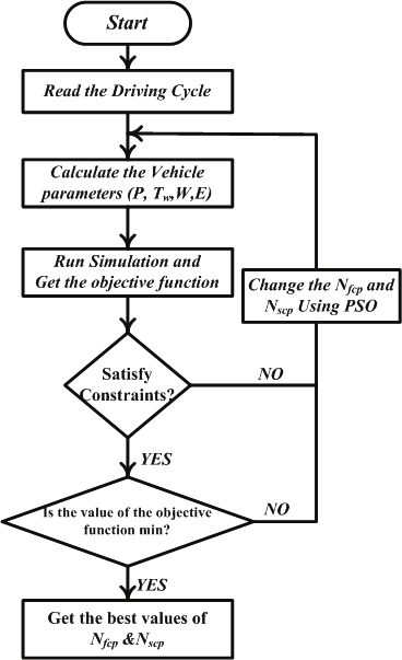
respectively. Figure 17 presents the flowchart of the execution of PSO, which evaluates the
optimal number of the FC units and the supercapacitor units by using MATLAB
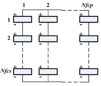
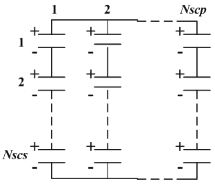
/SIMULINK. The layout of the fuel-cell stack and layout of the supercapacitor system are
shown in Fig.18 (a) and (b), respectively. The constraints of the optimization problems are
mentioned in [Hegazy & Van Mierlo, 2010].
Fig. 17. The flowchart of the execution of PSO [Hegazy et. al 2010]
Swarm Intelligence Based Controller for
Electric Machines and Hybrid Electric Vehicles Applications
187
(a)
(b)
Fig. 18. (a) Layout of the FC; (b) Layout of the SC
188
Electric Machines and Drives
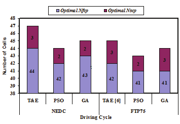
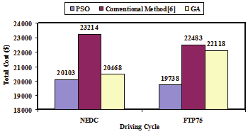
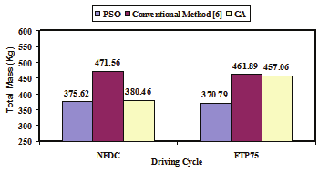
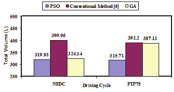
Based on minimizing the objective function F(x) in (68), the results of the optimal design and
components sizing of the FC/SC powertrain are shown in Fig.19. The analyses and
parameters of the FC and the SC are mentioned in [Hegazy & Van Mierlo, 2010].
(a) The optimal numbers of cells of FC and SC
(b) The cost of the FC/SC components
Swarm Intelligence Based Controller for
Electric Machines and Hybrid Electric Vehicles Applications
189
(c) The mass of the FC/SC components
(d) The mass of the FC/SC components
Fig. 19. The Comparative of the optimal design between different methods for FC/SC HEV
4.3 Optimal Power Control (OPC)
The second goal of the PSO is to minimize the vehicle fuel, hydrogen, consumption while
maintaining the supercapacitor state of charge. As a hybrid powertrain is under
consideration, a power management strategy is required to define what both the FC and SC
powers are. The global optimization algorithms, such as GA and dynamic programming
(DP), achieve an optimal power control for FC/SC hybrid electric vehicle, which leads to the
lowest hydrogen consumption and maintains the supercapacitor SOC [Sinoquet et. al 2009;
Sundstrom & Stefanopoulou 2006].
In this study, the optimal power control can be achieved by using PSO and GA for a given
driving cycle. Suppose that the degree of hybridization of the fuel cell is Kfc at time t and Ksoc, Proportional controller gain, which used to adapt the SOC during charging from the
FC. A balance equation can naturally be established, since the sum of power from both
sources has to be equal to the required power at all times:
190
Electric Machines and Drives
( t) = Pfc( t)
Psc( t) (70)
req
P
+
Pfc( t)
Kfc( t) =
(71)
( t)
req
P
The net energy consumed from the FC at time t can be computed as follows:
t
( )
(72)
Efc t
( ) =
Pfc t
∫
dt
η ( Pfc t())
0
The cost function can be expressed as follows:
N
Pfc
( k)
1
(73)
F ( x) =
∑
Opti
Δ T
2
Elow K = η ( Pfc
( k
0
Opti ))
The Optimal fuel cell power output, PfcOpti, is calculated based on the SOC of the
supercapacitor and power demand, Preq, as follows:
⎡
SOC
− SOC( k)
⎤
ref
(74)
Pfc
( k) = Kfc( k)
( k) + Ksoc( k) ( Pfc
− Pfc
) ⎢
⎥
Opti
req
P
max
min ⎢( SOC
− SOC
) / 2 ⎥
⎣
max
min
⎦
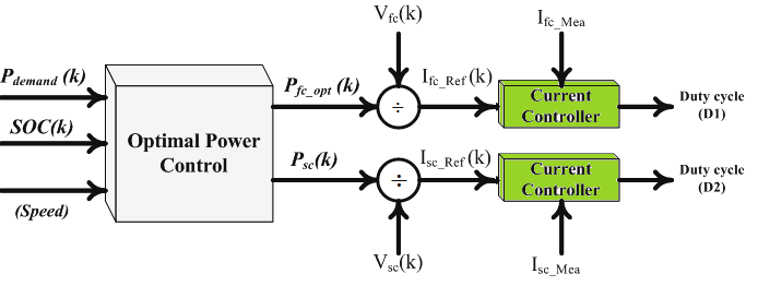
Fig. 20. The block diagram of the Optimal power Control
Where: N= T/ΔT is number of samples during the driving cycle, and ΔT=1s is the sampling
time.
The block diagram of the optimal power control based on optimization algorithm is shown
in Fig.20.
Based on minimizing the objective function F2(x) in (73), the results of the optimal power
sharing based PSO and the comparative study for the FC/SC powertrain are summarized in
Fig.21 [Hegazy et. al 2010].
Swarm Intelligence Based Controller for
Electric Machines and Hybrid Electric Vehicles Applications
191
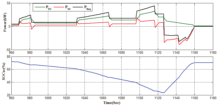
(a) The power sharing between FC and SC on NEDC driving cycle
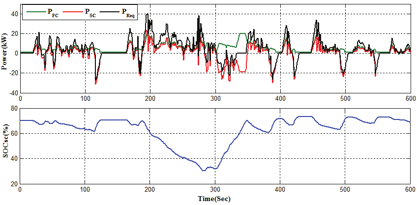
(b) The power sharing between FC and SC on FTP75 driving cycle
192
Electric Machines and Drives
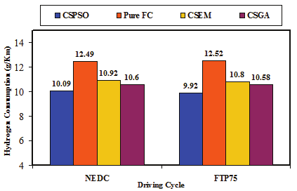
(c) The Comparative of the hydrogen consumption between control strategies
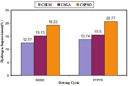
(d) The Hydrogen improvements with respect to pure fuel cell without SC
Fig. 21. The results of the optimal power Control for FC/SC
Swarm Intelligence Based Controller for
Electric Machines and Hybrid Electric Vehicles Applications
193
5. Conclusion
This chapter deals with the applicability of swarm intelligence (SI) in the form of particles
swarm optimization (PSO) used to achieve the best performance for the electric machines
and electric drives. In addition, by analyzing and comparing the results, it is shown that
control strategy based on PSO is more efficient than others control strategies to achieve the
optimal performance for fuel cell/supercapacitor hybrid electric vehicles (FCHEV).
It is very important to note that, these applications were achieved without any additional
hardware cost, because the PSO is a software scheme. Consequently, PSO has positive
promises for a wide range of variable speed drive and hybrid electric vehicles applications.
6. Index I
List of principal symbols
ωe : synchronous speed
ωr : rotor speed
p
: differential operator
rm , ra : main, auxiliary stator windings resistance
rr
: rotor winding resistance
Rfeq,d
: equivalent iron-loss resistance(d and q axis)
Llm ,Lla : main, auxiliary stator leakage inductance
Lmd ,Lm q : magnetizing inductance (d& q axis )
Llr
: rotor leakage inductance
K
: turns ratio auxiliary/main windings
Te
: electromagnetic torque
J
: inertia of motor
λds,qs
: stator flux(d and q axis)
λdr,qr
: rotor flux(d and q axis )
Vds,qs
: stator voltage (d and q axis)
ids,qs
: stator current (d and q axis)
M : mutual inductance
7. References
Amin. A. M. A., Korfally. M. I., Sayed. A. A. and Hegazy. O.T. M., (2009), Efficiency
Optimization of Two Asymmetrical Windings Induction Motor Based on Swarm
Intelligence, IEEE Transactions on Energy Conversion, Vol. 24, No. 1, March
2009
Amin. A. M. A., Korfally. M. I., Sayed. A. A. and Hegazy. O.T. M., (2006), Losses
Minimization of Two Asymmetrical Windings Induction Motor Based on Swarm
Intelligence, Proceedings of IEEE- IECON 06 , pp 1150 – 1155, Paris , France , Nov.
2006 .
Amin. A. M. A., Korfally. M. I., Sayed. A. A. and Hegazy. O.T. M., (2007), Swarm
Intelligence-Based Controller of Two-Asymmetrical Windings Induction Motor,
accepted for IEEE. EMDC07, pp 953 –958, Turkey, May 2007.
Eberhart. R, Kennedy. J, (1995), A New Optimizer Using Particles Swarm Theory, Proc.
194
Electric Machines and Drives
Sixth International Symposium on Micro Machine and Human Science (Nagoya,
Japan), IEEE Service Center, Piscataway, NJ, pp. 39-43,
A. Hamid Radwan H., Amin Amr. M. A., Ahmed Refaat S., and El-Gammal Adel A. A.
,(2006), New Technique For Maximum Efficiency And Minimum Operating Cost
Of Induction Motors Based On Particle Swarm Optimization (PSO)”, Proceedings
of IEEE- IECON 06 , pp 1029 – 1034, Paris , France , Nov. 2006.
Hegazy Omar, (2006), Losses Minimization of Two Asymmetrical Windings Induction
Motor Based on Swarm Intelligence, M.Sc., Helwan University, 2006.
Hegazy Omar, and Van Mierlo Joeri, (2010), Particle Swarm Optimization for Optimal
Powertrain Component Sizing and Design of Fuel cell Hybrid Electric Vehicle, 12th
International Conference on Optimization of Electrical and Electronic Equipment,
IEEE OPTIM 2010
Hegazy Omar, Van Mierlo Joeri, Verbrugge Bavo and Ellabban Omar, (2010), Optimal
Power Sharing and Design Optimization for Fuel Cell/Battery Hybrid Electric
Vehicles Based on Swarm Intelligence, The 25th World Battery, Hybrid and Fuel
Cell Electric Vehicle Symposium & Exhibition © EVS-25 Shenzhen, China, Nov. 5-9,
2010.
Kennedy. J and Eberhart .R, (2001), Swarm Intelligence, Morgan Kaufmann Publishers, Inc.,
San Francisco, CA
Kioskeridis, I; Margaris, N., (1996), Losses minimization in scalar-controlled induction
motor drives with search controllers" Power Electronics, IEEE Transactions,
Volume: 11, Issue: 2, March 1996 Pages: 213 – 220
Popescu. M, Navrapescu. V, (2000) ,A method of Iron Loss and Magnetizing Flux
Saturation Modeling in Stationary Frame Reference of Single and Two –Phase
Induction Machines”, IEE 2000, Conf. power Elec. & Variable Speed Drives, 140-
146
Sundstrom Olle and Stefanopoulou Anna, (2006), Optimal Power Split in Fuel Cell Hybrid
Electric Vehicle with different Battery Sizes, Drive Cycles, and Objectives,
Proceedings of the 2006 IEEE International Conference on Control Applications
Munich, Germany, October 4-6, 2006.
Van Mierlo Joeri, Cheng Yonghua, Timmermans Jean-Marc and Van den Bossche Peter,
(2006), Comparison of Fuel Cell Hybrid Propulsion Topologies with Super-
Capacitor, IEEE, EPE-PEMC 2006, Portorož, Slovenia
Wu Ying, Gao Hongwei, (2006) ,Optimization of Fuel Cell and Supercapacitor for Fuel-Cell
Electric Vehicles, IEEE Transactions On Vehicular Technology, Vol. 55, No. 6,
November 2006.
10
Operation of Active Front-End Rectifier in
Electric Drive under Unbalanced Voltage Supply
Miroslav Chomat
Institute of Thermomechanics AS CR, v.v.i.
Czech Republic
1. Introduction
Non-standard conditions in the power network such as voltage unbalance can negatively
affect operation of electric drives. The unbalance can be caused by a failure in the network
or by an unbalanced load in the electric vicinity of the affected drive. Unsymmetrical
voltages at the input of a voltage source inverter cause pulsations in the DC link voltage
when not properly taken care of. This may result in significantly reduced power capabilities
and, therefore, limited controllability of the drive. This text deals with the effects of
unbalanced voltage supply on the DC-link voltage pulsations, methods to address this
problem and the additionally imposed constraints in operating regions of the rectifier.
2. Control method
A simplified scheme of the drive under investigation is shown in Fig. 1. The front-end
controlled rectifier is connected to the mains through input filter inductors. The output
current of the rectifier supplies the DC current to the output inverter and maintains the
voltage across the DC-link capacitors constant at the same time. The value of this current
can be controlled by suitable switching of solid-state elements in the front-end stage.
i
power
input
front end
DC
DC bus
inverter
electric
network
impedance
machine
V
i
A
A
L
R
C DC
VDC
iB
VB
L
R
N
0
M
i
V
V
C
V
N
A
L
R
0
C
V
DC
DC
Fig. 1. Scheme of system under investigation.
Suitable control of the front-end AC/DC converter can be employed in order to draw
constant input power from the power network even at unbalanced voltage supply
196
Electric Machines and Drives
(Stankovic & Lipo, 2001; Lee et al., 2006; Cross et al., 1999; Song & Nam, 1999). The
switching functions for the front-end AC/DC converter are generated so that a constant
voltage across the DC bus is maintained. Series combinations of inductance and resistance
are considered at the input terminals of the inverter.
The system can be electrically described by the following set of ordinary differential
equations (Chomat & Schreier, 2005):
di
A
v − L
− Ri − v + v − v = 0
A
A
SA
N
0
, (1)
dt
di
B
v −
−
−
+
−
=
B
L
RiB
S
v B vN
0
v
0 , (2)
dt
C
di
−
−
−
+
−
= ,
(3)
C
v
L
R C
i
S