dt
⎢ bs
= ⎢
⎥
⎥ (14)
⎢ 0 ⎥
d
d
d
⎢ i
⎢
⎥
⎢
⎥
L cosθ
L sinθ
r +
L
0
⎥ ar
⎢ ⎥
0
sra
r
srb
r
r
r
⎢ dt
dt
dt
⎥
⎣
⎦
⎣ br
i
⎢
⎦
d
d
d
⎥
⎢− L sinθ
L cosθ
0
+
⎥
sra
r
srb
r
r
r
r
L
⎣ dt
dt
dt
⎦
The torque can be determined as
T
T
⎡ iar ⎤
(
d L ) ⎡ i ⎤
sr
as
=
(15)
e
T
⎢ i ⎥
⎢ ⎥
⎣ br ⎦ dθ r _ mech ⎣ ibs ⎦
Since θr = pθr_mech , where p is the number of pole pairs and θr is the electrical angle, and θr_mech is the actual angular displacement of the rotor, the Equation (15) can be rewritten
T
⎡ iar ⎤ (
d L ) T ⎡ i ⎤
T = .
sr
as
e
p ⎢
(16)
i ⎥
⎢ ⎥
⎣ br ⎦
dθ r ⎣ ibs ⎦
In expanded form, (16) becomes
T = [
p − i L ( i sinθ + i cosθ ) + i L ( i cosθ − i sinθ )]
e
as sra ar
r
br
r
bs srb ar
r
br
r
(17)
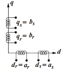
According to Krause et al. (1995), in order to obtain the motor mathematical model with
constant parameters, it is necessary to transform all the variables to the stationary reference
frame ( d-q) as shown in Fig. 2. That way θr = 0 .
A transformation matrix is necessary in order to establish the new reference frame. Thus
⎡ cosθ
sinθ ⎤
⎡
θ
θ ⎤
r
r
T = ⎢
⎥ ;
1
cos
sin
−
−
r
r
T =
(18)
−
⎢
⎥
⎣ sinθ
cosθ
θ
θ
r
r ⎦
⎣sin
cos
r
r ⎦
Space Vector PWM-DTC Strategy for Single-Phase Induction Motor Control
221
Fig. 2. Stationary reference frame ( d-q).
Applying the transformation matrix to Equations (14) and (17), then
⎡
d
dL s
dL
⎤
r +
0
srd
0
⎢ ds
dt
dt
⎥ s
s
⎢
⎥ ⎡ i
v
⎤
⎡
⎤
ds
ds
⎢
dL
dL
⎥ ⎢ ⎥
⎢
⎥
0
qs
r +
0
srq
s
s
⎢
qs
⎥ ⎢ i
v
⎥
⎢
⎥
qs
qs
dt
dt
= ⎢
⎥ ⎢ ⎥
⎢
⎥
(19)
0
s
⎢
srd
dL
r
dL
⎥ ⎢ i
ω
ω
dr
p
⎥
⎢
⎥
+
r s
L rq
r
r
p r r
L
⎢
⎥ ⎢ ⎥
⎢⎣0 ⎥
dt
dt
s
⎦ ⎢
⎥ ⎢ iqr ⎥
⎣ ⎦
⎢
srq
dL
r
dL
pω
ω
⎥
−
−
+
⎢
r s
L rd
p r r
L
r
r
dt
dt ⎥
⎣
⎦
T = [
s s
s s
p L i i − L i i ]
e
srq qs dr
srd ds qr (20)
where the superscript s denotes the stationary frame. The torque can also be expressed as
dω
(
p T − T )
r
=
+ ω
e
m
J
B r (21)
dt
This analytical approach represents the single-phase induction motor as an asymmetric two-
phase motor. The dq voltages, currents, and fluxes for stator and rotor are,
respectively: s
v
λ λ λ
λ
ds , sq
v s , sids , sqis , sidr , sqir , sds , sqs , sdr , sqr . The terms ds L , q
L s , r
L , sr
L d , sr
L q denote
the stator and rotor self-inductance and their respective mutual inductance. The stator and rotor resistance are denoted by ds
r , qrs , rr . The motor electromagnetic-torque and the load
torque are indicated by e
T and m
T , respectively. The moment of inertia, viscous friction
coefficient and the motor speed are, respectively: J , B and ω r .
One of the drawbacks of dealing with an asymmetric motor lies in the pulsating
electromagnetic torque that occurs due to the unbalance between the stator variables, as can
be seen in (19) and (20). To overcome this drawback and to create a symmetric model, a
transformation of the stator variables employing the mutual inductances was proposed by
Correa et al. (2004). The transformation matrix and its application can be written as
222
Electric Machines and Drives
⎡1 0⎤
S = ⎢
(22)
0 n⎥
⎣
⎦
s
s
⎡ v ⎤
⎡ v ⎤
ds
ds 1
⎢
⎥ = S ⎢
⎥ (23)
s
s
⎢ qs
v ⎥
⎢ vqs 1⎥
⎣
⎦
⎣
⎦
s
s
⎡ i ⎤
⎡ i ⎤
ds
1
−
ds 1
⎢ ⎥ = S ⎢
⎥ (24)
s
s
⎢ iqs ⎥
⎢ qs
i 1⎥
⎣ ⎦
⎣
⎦
s
s
⎡λ ⎤
⎡λ ⎤
ds
1
−
ds 1
⎢
⎥ = S ⎢
⎥ (25)
s
s
⎢λ ⎥
⎢λ
qs
qs 1 ⎥
⎣
⎦
⎣
⎦
L
The transformation element can be written as
srd
n =
.
sr
L q
When these transformations are applied to the mathematical model of the motor, the
unbalance between the main and auxiliary windings stator variables is eliminated. The new
symmetrical model of the single-phase induction motor acting as a two-phase system can be
given by the following equations:
s
⎡ v ⎤ ⎡ r
0
s
s
⎤ ⎡ i ⎤ d ⎡λ ⎤
ds 1
ds
ds 1
ds 1
⎢
⎥ = ⎢
⎥.⎢
⎥ +
⎢
⎥ (26)
s
⎢ v ⎥ ⎢ 0 r'
s
s
⎣
⎦ ⎣
⎥ ⎢ i ⎥ dt ⎢λ
qs 1
qs ⎦ ⎣ qs 1 ⎦
⎣ qs 1 ⎥⎦
s
⎡ v ⎤
⎡ ⎤
⎡
⎡
⎤
λ ⎤
⎡
⎡
⎤ λ ⎤
dr
r
0
s
s
i
r
dr
d
dr
0
1
s
⎢
⎥ = ⎢
⎥.⎢ ⎥ +
⎢
⎥ + ω ⎢
⎥. dr
⎢
⎥ (27)
s
⎢ v ⎥ ⎣0
s
s
r
r ⎦ ⎢ i ⎥ dt ⎢λ ⎥
⎣ 1
−
0
s
⎦ ⎢λ
⎣ qr
r
⎦
⎣ qr ⎦
⎣ qr ⎦
⎣ qr ⎥⎦
s
⎡λ ⎤ ⎡ L
0
s
⎤ ⎡
⎤
⎡ ⎤
ds
ds
ids
⎡ L
0
s
⎤ i
1
1
⎢
⎥ = ⎢
⎥.
srd
⎢
⎥ + ⎢
⎥. dr
⎢ ⎥ (28)
s
⎢λ ⎥ ⎢ 0 L'
s
⎣
⎦ ⎣
⎥ ⎢ i ⎥
⎦
⎣ 0
s
L
qs 1
qs
⎣ qs 1
srd ⎦ ⎢
⎦
⎣ qir ⎥⎦
s
⎡λ ⎤
⎡ ⎤
⎡
⎤
dr
⎡ L
0
s
⎤ i
⎡ L
⎤ i
r
dr
0
s
srd
ds 1
⎢
⎥ =
.⎢ ⎥ +
⎢
⎥
⎢
⎥.⎢
⎥ (29)
s
⎢λ ⎥ ⎣ 0
s
L ⎦ ⎢ i ⎥ ⎣ 0
s
L
⎣ qr
r
⎦
⎣ qr
srd ⎦ ⎢ i
⎦
⎣ qs 1 ⎥⎦
T = PL ( s s
s
s
−
e
srd iqs 1 idr
ids 1 i )
qr (30)
where
2
L' =
=
qs
n q
L s and
2
r' qs n qrs .
According to Correa et al. (2004), if the asymmetry that appears in the motor model depends
only on the number of turns of each stator winding, then the ratio presented by n will
corresponds approximately to refer the auxiliary winding variables to the main winding.
Also, if the inductances are slightly different, then L' ≈
qs
d
L s .
Space Vector PWM-DTC Strategy for Single-Phase Induction Motor Control
223
Observing Equation (26) there is an asymmetry between the stator resistances. This term can
be isolated
s
⎡ v ⎤
⎡
⎤
⎡
⎡
⎤
λ ⎤
ds
r
0
s
s
i
d
1
ds
ds 1
ds 1
⎢
⎥ = ⎢
⎥.⎢
⎥ +
⎢
⎥ + r
Δ (31)
s
⎢ v ⎥ ⎣ 0
s
s
r ⎦ ⎢ i ⎥ dt ⎢λ
⎣ qs 1
ds
⎦
⎣ qs 1 ⎦
⎣ qs 1 ⎥⎦
The term Δ r is given by
⎡
0
⎤
r
Δ = ⎢ 2
⎥ (32)
( n r −
⎢
r ) s
⎣
qs
ds iqs 1 ⎥⎦
When dealing with motor control, it is necessary to write the dynamic equations of the
induction motor in an arbitrary reference frame. This transformation allows the d-q variables
to be treated as dc signals, which is commonly used in control theory.
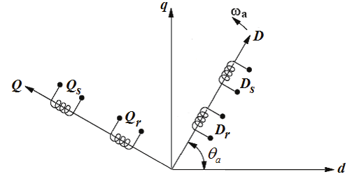
If Δ r is considered negligible, a symmetric model of the single-phase induction motor in the
arbitrary reference frame can be derived as shown in Fig. 3.
Fig. 3. Revolving reference frame.
The transformation matrix is given by
⎡cosθ
−sinθ ⎤
θ
θ ⎤
a
a
T = ⎢
⎥ ;
1
cos
sin
−
⎡
a
a
=
a
T
⎢
⎥ (33)
⎣sinθ
cosθ