ds
sqs
0
V
0 0 0 0 0
1
V
1 0 0 E 0
2
V
1 1 0 E E
3
V
0 1 0 0 E
4
V
0 1 1 -E 0
5
V
0 0 1 -E -E
6
V
1 0 1 0 -E
7
V
1 1 1 0 0
Table 1. Switching states and the adjacent vectors amplitude.
According to Jabbar et al. (2004), the reference vector and the adjacent vectors can be related
by the following equation:
*
s*
s*
=
⋅
+
⋅
p
T wmV
tds ds
V
tqs q
V s (43)
In Equation (19), t
s
s
ds and tqs are the durations in time in which the vectors
*
ds
V and
*
q
V s are
within period p
T wm . The period of duration of the zero vectors can be defined by
t =
−
−
0
p
T wm tds tqs (44)
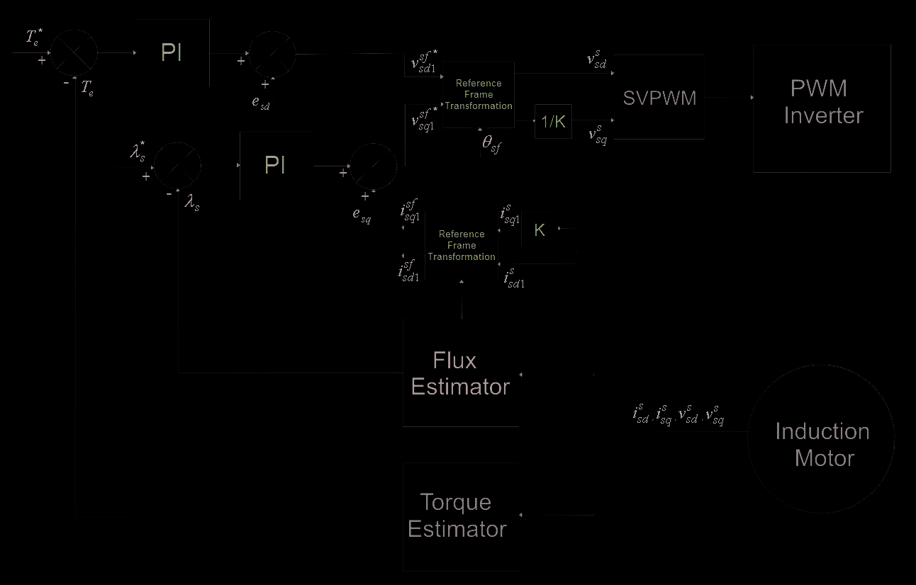
5. SVPWM-DTC Proposed Scheme
As mentioned in Section 3, to optimize the steady state performance and to diminish the
switching harmonics, a pulse width modulator can be applied. An improvement can be
achieved when torque and stator flux magnitude are controlled by PI controllers using a
closed-loop. The DTC strategy adapted to single-phase induction motors was discussed in
Jacobina et al. (1999) and Neves et al. (2002). Fig. 7 shows the proposed scheme. The essence of
DTC is kept, since its principle of accelerating the flux vector to increase torque is maintained,
and there is no need for speed or position signals. The output signals of the PI controllers can
be viewed as stator voltage components operating in Cartesian coordinates. After the reference
frame transformation, the PWM is fed with the stator voltage components in the stationary
frame. The control strategy relies on the stator flux orientation; therefore, the arbitrary
reference frame should be aligned with the stator flux vector, θ = θ
a
sf .
The condition to achieve the field orientation can be expressed by
sf
λ
= λ
sf
λ
= (45)
Ds 1
;
s
Qs 1
0
To determine the dynamic equations for the proposed technique, some algebraic
manipulations must be done. Taking the Equations (34), (35), (37), aligned with the stator
reference frame, the designed control signals can be derived:
⎡
⎤
sf
λ
λ
s
d s
s
L rd
r
L
r
L s
L d sf
sf
=
+
−
⎢
λ −
+
(46)
Ds
v 1
s
Ds
i 1
s
L rdiDs 1
τ σ
τ σ
⎥
ds s
dt
ds s r
L ⎣ srd
L
s
L rd
⎦
228
Electric Machines and Drives
sf
sf
di
L
dλ
sf
sf
Qs 1
srd
Qr
=
+
σ
+
Qs
v 1 qs
r Qs
i 1
qs
L
s
(47)
dt
r
L
dt
where,
2
σ = 1 − L /( L L )
s
srd
r sd (48)
Fig. 7. SVPWM-DTC proposed scheme.
By manipulating (46) and (47) in the synchronous frame, the designed control signals can be
obtained as:
λ
dλ
sf
s
s
v
=
+
+
Ds 1
eds (49)
τ σ
ds s
dt
sf
di
sf
sf
Qs 1
=
+
σ
+
Qs
v 1 qrs Qs
i 1
q
L s s
q
e s (50)
dt
assuming the terms eds and eqs as feed-forward elements and given by (51) and (52), and
considering the terms that indicate the asymmetry and disturbance negligible:
L
⎡ L
L L
⎤
srd
r
r ds sf
sf
e = −
⎢
λ −
+
ds
s
sD
i 1
srd
L isD 1 (51)
τ σ
⎥
ds s r
L ⎣ srd
L
s
L rd
⎦
L ⎡ r L
⎤
srd
r sd sf
=
qs
e
⎢
isQ 1⎥ (52)
r
L ⎣ srd
L
⎦
The torque as function of stator flux and currents is given by:
Space Vector PWM-DTC Strategy for Single-Phase Induction Motor Control
229
T = ( sf
sf
sf
sf
λ
−
λ
e
p Qs
i 1 Ds 1 Ds
i 1 Qs 1) (53)
A 4 poles, ¼ HP, 110 V, 60 Hz, asymmetrical 2-phase induction machine was used with the
following parameters expressed in ohms (Krause et al., 1995):
rds = 2.02;
Xld = 2.79; Xmd = 66.8;
rqs = 7.14;
Xlq = 3.22; Xmq = 92.9;
rŕ = 4.12;
Xĺr = 2.12.
The total inertia is J = 1.46 × 10⁻² kgm2 and Nsd/ Nsq = 1.18, where Nsd is the number of turns of the main winding and Nsq is the number of turns of the auxiliary winding. It was
considered a squirrel cage motor type with only the d rotor axis parameters.
In terms of stator-flux field-orientation
T = ( sf
e
p Qs
i λ
1
)
s (54)
According to (49) and (50), the stator flux control can be accomplished by sfDs
v 1 and torque
control by sf
sf
sf
Qs
v 1 . The stator voltage reference values *
vDs 1 and
*
Qs
v 1 are produced by two PI
controllers. The stator flux position is used in a reference frame transformation to orient the
dq stator currents. Although there is a current loop to decouple the flux and torque control,
the DTC scheme is seen as a control scheme operating with closed torque and flux loops
without current controllers (Jabbar et al., 2004).
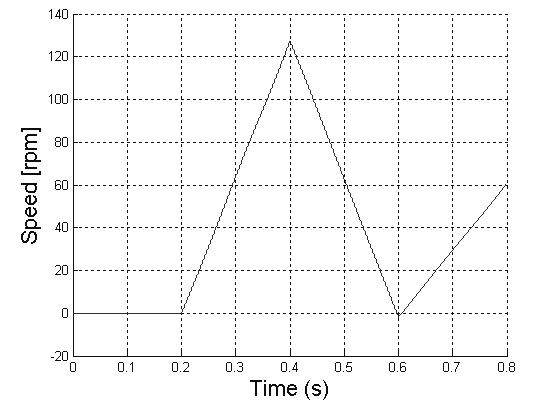
6. Simulation results
Some simulations were carried out in order to evaluate the control strategy performance.
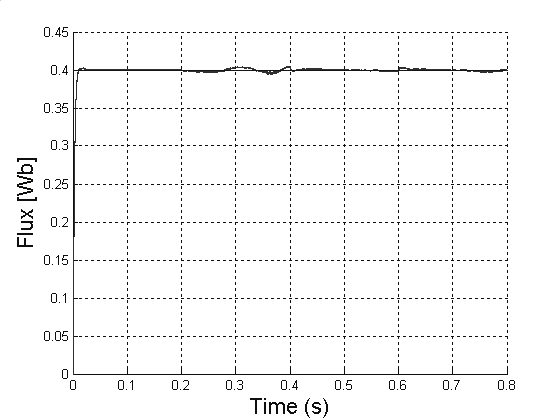
The motor is fed by an ideal voltage source. The reference flux signal is kept constant at 0.4
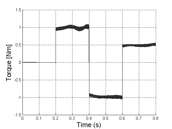
Wb. The reference torque signal is given by: (0,1,-1,0.5) Nm at (0,0.2,0.4,0.6)s, respectively.
The SVPWM method used produced dq axes voltages. The switching frequency was set to
5 kHz. Fig. 8 shows the actual value of the motor speed. In Fig. 9 and Fig. 10, the torque
Fig. 8. Motor speed (rpm).
230
Electric Machines and Drives
Fig. 9. Commanded and estimated torque (Nm).
Fig. 10. Commanded and estimated flux
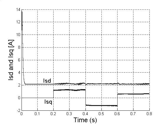
Fig. 11. Stator currents in stator flux reference frame.
Space Vector PWM-DTC Strategy for Single-Phase Induction Motor Control
231
waveform and the flux waveform are presented. Although the torque presents some
oscillations, the flux control is not affected. The good response in flux control can be seen.
Fig. 11 shows the relation between the d stator current component to the flux production
and the q stator current component to the torque production.
7. Conclusion
The investigation carried out in this paper showed that DTC strategy applied to a single-
phase induction motor represents an alternative to the classic FOC control approach. Since
the classic direct torque control consists of selection of consecutive states of the inverter in a
direct manner, ripples in torque and flux appear as undesired disturbances. To minimize
these disturbances, the proposed SVPWM-DTC scheme considerably improves the drive
performance in terms of reduced torque and flux pulsations, especially at low-speed
operation. The method is based on the DTC approach along with a space-vector modulation
design to synthesize the necessary voltage vector.
Two PI controllers determine the dq voltage components that are used to control flux and
torque. Like a field orientation approach, the stators currents are decoupled but not
controlled, keeping the essence of the DTC.
The transient waveforms show that torque control and flux control follow their commanded
values. The proposed technique partially compensates the ripples that occur on torque in
the classic DTC scheme. The proposed method results in a good performance without the
requirement for speed feedback. This aspect decreases the final cost of the system. The
results obtained by simulation show the feasibility of the proposed strategy.
8. References
Buja, G. S. and Kazmierkowski, M. P. (2004). Direct Torque Control of PWM Inverter-Fed
AC Motors - A Survey, IEEE Transactions on Industrial Electronics, vol. 51, no. 4,
pp. 744-757.
Campos, R. de F.; de Oliveira, J; Marques, L. C. de S.; Nied, A. and Seleme Jr., S. I. (2007a).
SVPWM-DTC Strategy for Single-Phase Induction Motor Control, IEMDC2007,
Antalya, Turkey, pp. 1120-1125.
Campos, R. de F.; Pinto, L. F. R.; de Oliveira, J.; Nied, A.; Marques, L. C. de S. and de Souza,
A. H. (2007b). Single-Phase Induction Motor Control Based on DTC Strategies,
ISIE2007, Vigo, Spain, pp. 1068-1073.
Corrêa, M. B. R.; Jacobina, C. B.; Lima, A. M. N. and da Silva, E. R. C. (2004).Vector Control
Strategies for Single-Phase Induction Motor Drive Systems, IEEE Transactions on
Industrial Electronics, vol. 51, no. 5, pp. 1073-1080.
Charumit, C. and Kinnares, V. (2009). Carrier-Based Unbalanced Phase Voltage Space
Vector PWM Strategy for Asymmetrical Parameter Type Two-Phase Induction
Motor Drives, Electric Power Systems Research, vol. 79, no. 7, pp. 1127-1135.
dos Santos, E.C.; Jacobina, C.B.; Correa, M. B. R. and Oliveira, A.C. (2010). Generalized
Topologies of Multiple Single-Phase Motor Drives, IEEE Transactions on Energy
Conversion, vol. 25, no. 1, pp. 90-99.
Jabbar, M. A.; Khambadkone, A. M. and Yanfeng, Z. (2004). Space-Vector Modulation in a
Two-Phase Induction Motor Drive for Constant-Power Operation, IEEE
Transactions on Industrial Electronics, vol. 51, no. 5, pp. 1081-1088.
232
Electric Machines and Drives
Jacobina, C. B.; Correa, M. B. R.; Lima, A. M. N. and da Silva, E. R. C. (1999). Single-phase
Induction Motor Drives Systems, APEC´99, Dallas, Texas, vol. 1, pp. 403-409.
Krause, P. C.; O. Wasynczuk, O. and Sudhoff, S. D. (1995). Analysis of Electric Machinery.
Piscataway, NJ: IEEE Press.
Neves, F. A. S.; Landin, R. P.; Filho, E. B. S.; Lins, Z. D.; Cruz, J. M. S. and Accioly, A. G. H.
(2002). Single-Phase Induction Motor Drives with Direct Torque Control,
IECON´02, vol.1, pp. 241-246.
Takahashi, I. and Noguchi, T. (1986). A New Quick-Response and High-Efficiency Control
Strategy of an Induction Motor, IEEE Transactions on Industry Applications, vol.
IA-22, no. 5, pp.820-827.
Noguchi, T. and Takahashi, I. (1997), High frequency switching operation of PWM inverter
for direct torque control of induction motor, in Conf. Rec. IEEE-IAS Annual
Meeting, pp. 775–780.
Wekhande, S. S.; Chaudhari, B. N.; Dhopte, S. V. and Sharma, R. K. (1999). A Low Cost
Inverter Drive For 2-Phase Induction Motor, IEEE 1999 International Conference on
Power Electronics and Drive Systems, PEDS’99, July 1999, Hong Kong.
Hu, J. and Wu, B. (1998). New Integration Algorithms for Estimating Motor Flux over a
Wide Speed Range. IEEE Transactions on Power Electronics, vol. 13, no. 5, pp. 969-
977.
12
The Space Vector Modulation PWM Control
Methods Applied on Four Leg Inverters
Kouzou A, Mahmoudi M.O and Boucherit M.S
Djelfa University and ENP Algiers,
Algeria
1. Introduction
Up to now, in many industrial applications, there is a great interest in four-leg inverters for
three-phase four-wire applications. Such as power generation, distributed energy systems
[1-4], active power filtering [5-20], uninterruptible power supplies, special control motors
configurations [21-25], military utilities, medical equipment[26-27] and rural electrification
based on renewable energy sources[28-32]. This kind of inverter has a special topology
because of the existence of the fourth leg; therefore it needs special control algorithm to fulfil
the subject of the neutral current circulation which was designed for. It was found that the
classical three-phase voltage-source inverters can ensure this topology by two ways in a way
to provide the fourth leg which can handle the neutral current, where this neutral has to be
connected to the neutral connection of three-phase four-wire systems:
1. Using split DC-link capacitors Fig. 1, where the mid-point of the DC-link capacitors is
connected to the neutral of the four wire network [34-48].
T
T
T
a
b
c
S
S
S
a
b
c
C
Va
V
Vb
g
N
VcN
Vc
C
VbN
T
a
T
Tc
b
VaN
Fig. 1. Four legs inverter with split capacitor Topology.
T
T
T
a
T
b
c
f
S
S
S
a
Sb
c
f
Va
V
V
g
b
Vcf
Vc
Vbf
Vaf
T
V f
a
T
T
T
T
a
b
c
f
Fig. 2. Four legs inverter with and additional leg Topology.
234
Electric Machines and Drives
2. Using a four-leg inverter Fig. 2, where the mid-point of the fourth neutral leg is
connected to the neutral of the four wire network,[22],[39],[45],[48-59].
It is clear that the two topologies allow the circulation of the neutral current caused by the
non linear load or/and the unbalanced load into the additional leg (fourth leg). But the first
solution has major drawbacks compared to the second solution. Indeed the needed DC side
voltage required large and expensive DC-link capacitors, especially when the neutral
current is important, and this is the case of the industrial plants. On the other side the
required control algorithm is more complex and the unbalance between the two parts of the
split capacitors presents a serious problem which may affect the performance of the inverter
at any time, indeed it is a difficult problem to maintain the voltages equally even the voltage
controllers are used. Therefore, the second solution is preferred to be used despite the
complexity of the required control for the additional leg switches Fig.1. The control