.
.
.
.
.
.
.
.
.
.
.
.
.
.
.
.
.
.
.
.
.
.
.
.
.
.
.
.
.
.
.
.
.
.
.
.
.
.
.
.
.
. . . .
. . . . . . .
. . . . . . . . . . . . . .
. . . . . . . . . . . . . . . . . . . . . . . .
. . . . . . . . . . . . . . . . . . . . . . .
. . . . . . . . . . . . . . . . .
.
. . . .
. . . .
.
.
.
.
.
.
.
.
.
.
.
.
.
.
.
.
.
.
.
.
.
.
.
.
.
.
.
.
.
.
.
.
.
.
.
.
.
.
.
.
i
.
.
.
.
.
.
.
.
.
.
.
.
. a
.
.
.
.
.
.
.
.
.
.
.
. . . .
. . . . . . .
. . . . . . . . . . . . . . . . . . . . . . . . . . . . . . . . . . . . . .
. . . . . . . . . . . . . . . . . . . . . . .
. . . . . . . . . . . . . . . . .
.
. . . .
. . . .
.
.
.
.
.
.
.
.
.
.
.
.
.
.
.
.
.
.
.
.
.
.
.
.
.
.
.
.
.
.
.
.
.
.
.
.
.
.
.
.
.
.
.
.
.
.
.
.
.
.
.
.
. . . . . . . . . . . . . . . . . . . . . . . . .
. . . . . . . . . . . . . . . . . . . . . . . .
. . . . . . . . . . . . . . . . . . . . . . .
. . . . . . . . . . . . . . . . .
.
. . . .
. . . .
.
.
.
.
.
.
.
.
.
.
.
.
.
.
.
.
.
.
.
.
.
.
.
.
.
.
.
.
.
.
.
.
.
.
.
.
.
.
.
.
1) [THS720P].CH1 100 V 2 mS
1) [THS720P]
. .CH1 10. 0 V 5 m. S
.
.
.
.
.
2) [THS720P].CH2 5 A 2 mS
2) [THS720P].CH2 1 A 5 mS
(a) (b)
Fig. 17. Voltage and current for: a) uncompensated motor; b) compensated motor
6. Comments
This study proved that direct injecting capacitance reactance through auxiliary winding
does improve the power factor of the induction motor; it also increases the ratio torque over
current. What is also very interesting is this method achieves a “flat” variation of power
factor with respect of load variation. This is a very important improvement given the fact
that majority of induction motors do not work at constant full load where the classic design
produces maximum performances.
However, this method introduces extra copper losses reducing the overall efficiency and
increasing the operation temperature.
This study did not intended to elucidate the full effect of the method upon the torque
especially the existence of the influence produced by the current flowing through auxiliary
windings. The only aspect clearly noticed was the torque ripple introduced by the “single-
phase” auxiliary winding connection.
Further more, the same method was applied to a synchronous reluctance motor
(Ogunjuyigbe et al, 2010). The same type of stator winded similarly as above was used with
a salient milled rotor obtained from the corresponding squirrel cage induction motor. The
experimental results show an improvement of the power factor from 0.41-0.69 to 0.93-0.97
for the entire loading range.
40
Electric Machines and Drives
The economic benefits are related with the savings on demand especially for places where a
large number of three-phase induction motors are used under variable loading.
7. References
M. A El-Sharkawi, S. S Venkata, T. J Williams, and N. G Butler, “An adaptive Power Factor
Controller for Three-Phase Induction Generators”, Paper 84 SM 672-2 presented at
the IEEE/PES Summer Meeting, Seattle, Washington, July 15-20, 1984.
Fuchs, E.F. Hanna, W.J.; “Measured efficiency improvements of induction motors with
thyristor/triac controllers”, , IEEE Transaction on Energy Conversion, Volume 17,
Issue 4, Dec. 2002 pp. 437 – 444
Suciu, C.; Dafinca, L.; Kansara, M.; Margineanu, I.; “Switched capacitor fuzzy control for power
factor correction in inductive circuits”, IEEE 31st Annual Power Electronics Specialists Conference, 2000. Vol. 2, pp. 773 - 777
C. Suciu, M. Kansara, P. Holmes and W. Szabo, “Performance Enhancement of an Induction
Motor by Secondary Impedance Control, IEEE Trans. On Energy Conversion, Vol. 17,
No. 2, June 2002
J. Reinert, M.J. Parsley, ‘‘Controlling the speed of 8×1 induction motor by resonating the
rotor &wit,” in IEEE Transactions on Industry Applications, Vol. 31, No. 4,
July/August 1995, pp. 887-891.
E. Muljadi, T.A. Lipo, D.W. Novotny, "Power Factor Enhancement of Induction Machines by
Means of Solid State Excitation," IEEE Trans. on Power Electronics, Vol. 4, No. 4, pp.
409418, Oct. 1989.
I. M Tamrakan and O.P Malik, “Power Factor Correction of Induction motors Using PWM
Inverter Fed Auxiliary Stator Winding”, IEEE Transaction on Energy Conversion, Vol.
14, No.3, Sept, 1999, pp. 426-432
J. B. Medarametla, M. D. Cos, and Baghzouz, “Calculations and measurement of unity plus
three-phase induction motor,” IEEE Transactions on Energy Conversion, vol. 7, no. 4,
pp. 732-738, 1992.
S. D. Umans, and H. L. Hess, “Modelling and analysis of a the Wanlass three-phase
induction motor configuration,” IEEE Transaction on Power Apparatus and Systems,
vol. 102, no. 9, pp. 2912-2916, 1983.
R. Spée and A. Wanllace, “Comparative Evaluation Of Power-Factor Improvement
Techniques For Squirrel cage Induction Motors”, Industry Applications Society
Annual Meeting, 1990.
A.A. Jimoh and D.V. Nicolae, “Performance Analysis of a Three-Phase Induction Motor with
Capacitance Injection”, OPTIM’06, 10th International Conference on Optimization of
Electrical and Electronic Equipments, Brasov, Romania, May 17-20, 2006
D.V. Nicolae and A.A. Jimoh, “Three-Phase Induction Motor with Power Electronic
Controlled Single-Phase Auxiliary Stator Winding”, PESC’07, The 38th IEEE Power
Electronics Specialists Conference, Orlando, USA, June 17-21, 2007
A.S.O. Ogunjuyigbe, A.A. Jimoh, D.V. Nicolae and E.S. Obe, “Analysis of Synchronous
Reluctance Machine with Magnetically Coupled Three Phase Windings and Reactive
Power compensation”, IET Electric Power Applications, 2010, Vol. 4, Iss. 4, pp 291-303
3
Magnetic Reluctance Method for Dynamical
Modeling of Squirrel Cage Induction Machines
Jalal Nazarzadeh and Vahid Naeini
Faculty of Engineering
Shahed University, Tehran
Iran
1. Introduction
Nowadays, induction machines play important role in electromechanical energy conversion in
industry. These machines are often operated in critical conditions where can cause unexpected
failures and outages. Generally, stator and bearing faults, broken rotor bar and end-rings,
air-gap irregularities are some of the major faults in an induction machine (Al-Shahrani, 2005;
Sprooten, 2007) which may be situated the induction machines in out of service (Siddique
et al., 2005). Fourier analysis for stator currents (Bellini et al., 2001; Benbouzid, 2000; Jung
et al., 2006), torque and rotor speed, acoustic noise and temperature analysis (Siddique et
al., 2005) are some classical techniques which introduced for identification and diagnosis of
induction machines faults. Additionally, other heuristic methods were proposed to monitor
of the induction machines for fault detection. For instance, neural network modelling were
applied to monitor an induction machine for fault detection (Su & Chong, 2007). Also, space
vector of rotor magnetic field (Mirafzal & Demerdash, 2004) based on artificial intelligent
approaches and pendulous oscillation of the rotor magnetic field were proposed. Recently,
a new technique based on the analysis of three-phase stator current envelopes was presented
(Mirafzalet & Demerdash, 2008). In all monitoring and fault detection techniques, we need
to tune up the monitoring systems based on response of induction machines for proper
operations. However, experimental set up for testing any arbitrary fault conditions are not
practical. Thus, an accuracy dynamic and steady state models of induction machines are very
important for this propose.
Also, for dynamical modelling of induction machines, space harmonic distribution, core
saturation and loss are often neglected in abc quantitative and two-axis methods (Krause et
al., 1995). Thus, these approaches do not have an efficient accuracy for modelling of induction
machines in asymmetrical and non-linear conditions. For considering distribution rotor bars,
coupled magnetic circuit method (Muñoz & Lipo, 1999), abc quantitative based on rotor bar
currents (Alemi & Nazarzadeh, 1996) can be utilized. Furthermore, winding function method
may be used to include the stator winding distribution effect in the air gap flux (Luos et al.,
1995). However, in all mentioned methods, the core saturation, stator and rotor teeth effects
and distributions of the rotor and stator windings can not be investigated, simultaneously.
Also, Finite Element Method (FEM) is a professional technique for analysis of any
electromagnetic systems, which needs to magnetic and geometry details of the systems (Faiz
42
Electric Machines and Drives
et al., 2002). This method is very accurate and flexible, but due to complexity, the dynamical
modelling of an induction machine is quite complicated. Contrary to FEM, the Magnetic
Equivalent Circuit Method (MECM) can apply to analysis of the electro magnetics problems
with lower complexity. Magnetic saturation, space harmonics in stator and rotor teeth, stator
windings and distributed structure of a squirrel-cage rotor can be considered by MECM for
modelling and analysis of any induction machines (Jeong et al., 2003; Ostovic, 1989). In this
approach, the non-linear reluctances of flux paths use to configure magnetic equivalent circuit.
This method has less complexity than FEM for dynamical modelling of induction machines.
Therefore, developing an exact details model of induction machine for analysis of transient,
sensitivity and fault diagnosis in the asymmetrical conditions are very essential.
The present chapter introduces methodology of MECM for modelling and analysis of
asymmetrical non-linear systems in transient and steady state conditions. MECM is very
suitable method for finding a generalized accurate dynamical model of squirrel cage induction
machines with asymmetrical conditions. For evaluation of the method, several simulations
in linear and non-linear conditions are made. Also, some simulations results for induction
machines with broken bar faults and core saturation conditions are included to illustrate
capability of the method in asymmetrical conditions.
2. Electric and magnetic based model of squirrel cage induction machines
For detailed modelling of any electromagnetic systems, we have to find a correlation between
electric and magnetic variables of the system. Generally, a set of non-linear differential
equations presents dynamical model of a electromagnetic system that by using numerical
analysis, transient response of the electrical variables can be obtained. In addition, non-linear
algebraic equations illustrate non-linear relations between electrical and magnetic variables.
MECM provides an augmented model of the electromagnetic systems, in which we can
achieve all variables of the systems in transient and steady state, simultaneously. Also, the
main advantages of MECM for modelling of induction machines are; simple algorithm for
including distribution winding, stator and rotor teeth effects and magnetic core saturation
phenomena. Global non-linear model of squirrel cage induction machines can be offered
in algebraical (magnetic) and differential (electric) equations which will be presented in the
following sections.
3. Magnetic equivalent circuit of induction machines
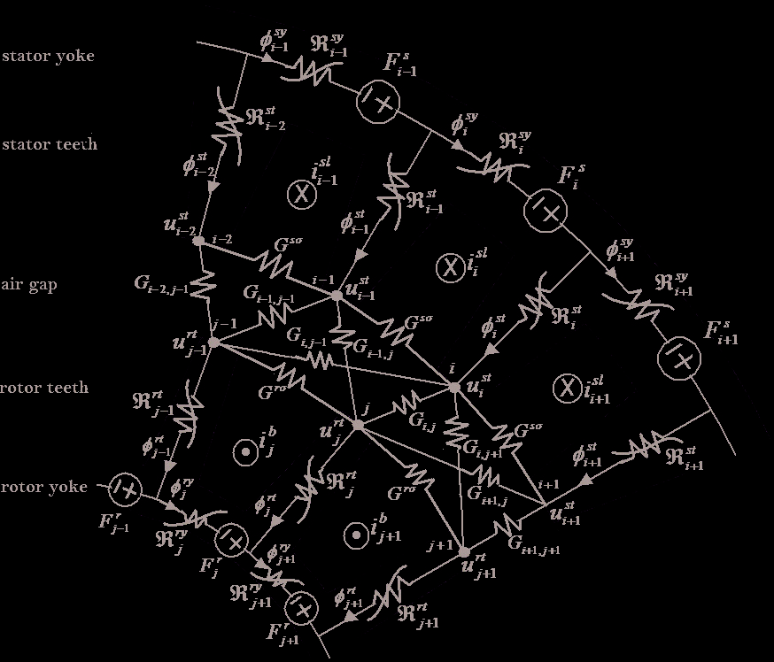
Fig. 1 shows a part of rotor and stator structures for a typical squirrel cage induction
machine that magnetic circuit elements are presented for rotor and stator teeth and yoke.
Numbers of rotor and stator teeth are considered by h and l, respectively. Also in this figure, magnetic mutual permeances of rotor and stator teeth in air gap are shown. Due to non-linear
characteristics of flux and magnetic current in iron core, permeances of the rotor and stator in
the magnetic cores are illustrated as non-linear elements. Gi, j is linear permeance of flux path between ith stator and jth rotor teeth in the air gap.
3.1 Magnetic node equations
Due to the fact that magnetic permeances of each stator and rotor teeth make several magnetic
loops in the air gap, we apply node magnetic potential equations to the each air gap nodes for
Magnetic Reluctance Method for Dynamical Modeling of Squirrel Cage Induction Machines
43
Rotor Axis
J t
Stator Axis
Fig. 1. Magnetic equivalent circuit of induction machine
simplicity in algebraic magnetic equations. For instance, sum of magnetic fluxes in ith air gap
node (stator tooth) have to be zero; thus we can write:
us −
−
− )
− )
i
usi+1 Gsσ + usi usi− 1 Gsσ + ( usi ur 1 Gi 1 + · · · + ( usi url Gil = φsti (1)
where us, ur and φst are magnetic potential of stator, rotor and flux of ith stator tooth and i
i
i
Gsσ and Gi, j are permeances of stator neighbour slots and mutual permance between ith stator with jth rotor teeth, respectively.
Similar Eq. (1), continuity principle in the teeth fluxes at ith rotor node yields as:
ur −
−
− )
− )
i
uri+1 Grσ + uri uri− 1 Grσ + ( uri us 1 Gi 1 + · · · + ( uri ush Gih = −φrti (2)
In Eq. (2), φst and Grσ are flux of ith rotor tooth and permeance of rotor slot, respectively.
i
Consequently, node potential equations for equivalent circuit of Fig. 1 along the air gap can
be written as:
A ssU st + A srU rt = Ψ st
(3)
A rsU ss + A rrU rt = −Ψ rt
(4)


44
Electric Machines and Drives
where A ss ∈ R h×hâ ˘
Ać, A rr ∈ R l×l and A sr ∈ R h×l are air gap permeance coefficients matrices that we can written as:
⎡
⎤
l
⎢ 2 Gsσ+ ∑ G
⎢
1, j
−Gsσ
0
· · · 0
0
−Gsσ
⎥
⎢
j=1
⎥
⎢
⎥
l
⎢
⎥
⎢
−Gsσ
2 Gsσ+ ∑ G 2, j
−Gsσ · · · 0
0
0
⎥
⎥
A ss = ⎢
j=1
⎢
⎥
(5)
⎢
.
.
.
.
.
.
.
⎥
⎢
.
.
.
.
⎥
.
.
.
.
⎢
.
.
.
.
.
.
⎥
⎣
⎥
l
−
⎦
Gsσ
0
0
· · · 0 −Gsσ 2 Gsσ+ ∑ Gh, j
j=1
⎡
⎤
h
⎢ 2 Grσ+ ∑ G
⎢
i,1
−Grσ
0
· · · 0
0
−Grσ
⎥
⎢
i=1
⎥
⎢
h
⎥
⎢
−
⎥
Grσ
2 Grσ+ ∑ Gi,2
−Grσ · · · 0
0
0
⎥
A
⎢
⎥
rr = ⎢
i=1
(6)
⎢
⎥
.
.
.
.
.
.
⎢
.
.
.
. .
.
.
.
⎥
⎢
.
.
.
.
.
.
.
⎥
⎣
⎥
h
⎦
−Grσ
0
0
· · · 0 −Grσ 2 Grσ+ ∑ Gi, l
i=1
⎡
⎤
G 1,1
G 1,2
· · · G 1, l
⎢
⎢ G