..
..
. .
..
.. ⎥
⎣
⎥
0
0
0
· · ·
1
0 ⎦
0
0
0
· · · − 1
1
3.3 Teeth and yoke flux relations
For completing of the magnetic model of an induction machine, we need to find a relation
between teeth and yoke fluxes in mesh equations (Eqs. (21) and (22)). Attention to Fig. 1,
the relations between stator teeth and yoke fluxes can be obtained by applying magnetic flux
continuity principle in the yoke nodes. Thus, we have:
φsy = φst + φsy
(32)
i
i
i+1


48
Electric Machines and Drives
Similarly, relation between the rotor fluxes are:
φry = φrt + φry
(33)
j+1
j
j
Eqs. (32) and (33) can be presented in matrix form as:
Ψ st = A sytΨ sy
(34)
Ψ rt = A rytΨ ry
(35)
where A syt ∈ R h×h and A ryt ∈ R l×l can be written as
⎡ −
⎤
1
1
0
· · ·
0
0
⎢
⎢ 0
− 1
1
· · ·
0
0 ⎥
⎢
⎥
⎢ 0
0
− 1 · · ·
0
0 ⎥
⎥
A ryt = −A syt = ⎢
⎢ .
.
.
.
.
.
⎥
(36)
⎢ ..
..
..
. .
..
.. ⎥
⎣
⎥
0
0
0
· · · − 1
1 ⎦
1
0
0
· · ·
0
− 1
In a squirrel cage induction machine, a stator winding is not concentrated in single slot, but it
is distributed along air gap for harmonics reduction, full utilization of core and reduction of
mechanical stress to the winding. Thus, flux of stator coil equals the sum of fluxes of stator
teeth in the coil pitch. If three phase flux vector of the stator windings denotes as Ψ3 φ, we can
find a matrix relation between stator teeth and windings fluxes as:
Ψ3 φ = M cf Ψ st
(37)
where M c f ∈ R3 ×h is a connected matrix which can be obtained based on the connection diagram of stator windings.
4. Core saturation characteristic
Generally, magnetic cores of any electrical machines have non-linear characteristic curve
( B−H), thus the elements of reluctance matrices in Eqs. (23) and (24) are depended to their
fluxes. For inserting the non-linearity characteristic of the magnetic core to mesh equations,
a non-linear permeability dependent to the core field density are used. For this purpose, a
non-linear permeability is defined as:
μ( B) = μ 0 μr( B) = ∂B
∂
(38)
H
So, the reluctances of flux path in the stator and rotor cores can be written as:
k = sy, st, ry, rt
Bk =
Lki
i
(39)
μ( Bk) Ak
i = 1, 2, . . .
i
i
where Lk and Ak are ith length and cross section of flux path in the stator and rotor cores, i
i
respectively. Tangent, exponential and piecewise linear functions may be used to approximate
the saturation curve (Chen et al., 2005). In this chapter, the magnetic core permeability is


Magnetic Reluctance Method for Dynamical Modeling of Squirrel Cage Induction Machines
49
2.5
2.0
1.5
Tesla
B
1.0
0.5
0.0
0
5000
10 000
15 000
20 000
25 000
30 000
A
H
m
Fig. 3. Core saturation curve
considered as:
μ ( B) = b × ea×B 2
(40)
where a and b are two constants which can be chosen for the best fitting of the saturation curve ( B−H) with this relation. By integrating Eq. (38) and combining with Eq. (40), the magnetic
field intensity H can be written as
√
√
πEr f
a × B
H ( B) =
1
√
μ (
(41)
B) dB =
2 b a
where Er f is error function which is defined as: (Gautschi, 1964):
Er f ( B) =
eB 2 dB
(42)
For instance, Fig. 3 shows a saturation curve ( B − H) for a silicon steel core that we can find
two constants in Eq. (40) for the best fitting of the saturation curve. In this case, the two
constants can be found as:
a = − 0.8
(43)
b = 1000
5. Excitation vectors of reluctance network
For determining relations between three phase currents with ampere-turn in the stator
magnetic circuits, we give a contour between ( i − 1) th and ith stator teeth, yoke and slot in Fig. 1. Also, we suppose that combining of three phase conductors are placed in the stator
slots. Therefore, by applying Ampere’s law to this contour, ( i) th ampere-turn of the stator magnetic circuits ( Fs) in Eq. (21) can be expressed as:
i
Fs =
i
waiia + wbiib + wciic
(44)
50
Electric Machines and Drives
Fig. 4. Single layer distributed winding with 24 slot
where wa, wb and wc are conductor numbers of phase a, b and c in the ith stator slot, i
i
i
respectively. Values and signs of these parameters will depend to connections and directions
of windings in the ith slot. For instance, Fig. 4 shows a single layer three phase winding with
two poles and 24 slots, which can generate a rotating magnetic field in the air gap. In this
case, relation between ampere-turn of the stator magnetic circuits and stator currents can be
determined as:
⎡
⎤
⎡
⎤
Fs
−wa
0
0
⎢ 1
⎢ Fs ⎥
⎢ −wa 0
0 ⎥
⎢ 2 ⎥
⎢
⎥
⎢ Fs ⎥
⎢
0
0
wc ⎥ ⎡
⎤
⎢ 3 ⎥
⎢
⎥
ia
⎢ . ⎥
⎢
.
.
. ⎥
⎢ . ⎥ = ⎢
.
.
. ⎥ ⎣ i ⎦
(45)
⎢ . ⎥
⎢
.
.
. ⎥
b
⎢
⎥
⎢
⎥
i
⎢ Fs ⎥
⎢
⎥
c
22
0
wb
0
⎣
⎥
⎢
⎥
Fs ⎦
⎣ −
⎦
23
wa
0
0
Fs
−
24
wa
0
0
Thus, the stator ampere-turn vector (F s) in Eq. (21) may be presented as
F s = W ci s
(46)
where W c ∈ R h× 3 , is a connection matrix that shows number of conductors in all of the stator slots. Also, i s is a vector of three phase currents that we can arrange as:
T
i s =
ia
ib
ic
(47)
In single layer winding, each slot can carry only one phase current, thus rows of the connection
matrix in Eq.
(46) have only one non-zero element.
These non-zero elements can be
determined by attention to stator winding topology.
In other respect, currents of rotor bars in squirrel cage induction machines are equal to
current of conductors in the rotor slots. Therefore, similar to above mentioned method; the
ampere-turn in rotor slots (F r) in Eq. (22) can be determined by:
F r = i b
(48)

Magnetic Reluctance Method for Dynamical Modeling of Squirrel Cage Induction Machines
51
where i b , the rotor bars currents vector is defined as
T
i b =
ib
ib
· · · ib
(49)
1
2
l
Substituting Eqs. (34), (35), (46) and (48) into (21) and (22) and combining with Eqs. (3) and
(4), the magnetic algebraic equations of squirrel cage induction machines in matrix form can
be augmented as
⎡
⎤⎡
⎤ ⎡
⎤
A φsy+A φstA syt
0
A ust
0
Ψ sy
W ci s
⎢
⎢
0
A φ
⎥⎢
⎥ ⎢
⎥
ry +A φrtA ryt
0
A urt
Ψ ry
i b
⎣
⎥⎢
⎥ ⎢
⎥
−A
⎦⎣
⎦ = ⎣
⎦
(50)
syt
0
A ss
A sr
U st
0
0
A ryt
A rs
A rr
U rt
0
Due to core saturation characteristic is a non-linear curve, the matrix Eq. (50) is non-linear and
some coefficient matrices depends to the core fluxes density. Thus, ordinary methods cannot
be employed for solving Eq. (50). Furthermore, rotor and stator currents are depended to
stator three phase source voltages and rotor speed in differential equation forms. Therefore,
for detailed analysis of squirrel cage induction machine, it is necessary to solve an electric,
mechanic and magnetic algebraic differential equations, simultaneously
6. Electrical voltage equations of squirrel cage induction machines
Generally, a set of differential equations in an electrical machine is used to describe rates of
the electrical and mechanical variables. These equations establish the relationship between
fluxes, currents and the three phase source voltage variables. In the next section, rotor and
stator voltage relations are be derived.
6.1 Stator voltage equations
For an induction machine, we can write electrical differential equations in stator windings as:
V s = R si s + d Λ
dt s
(51)
where V s and R s are voltage and stator resistances matrix, respectively which are defined by T
V s =
va
vb
vc
(52)
R s = diag
ra
rb
rc
(53)
Moreover, Λ s is linkage flux vector and equals to the product of turn number of stator
windings and the phase fluxes. Thus, we can write:
Λ
T
s =
λa λb λc
(54)
Λ s = wcΨ3 ϕ
(55)
By substituting Eqs. (34) and (37) into (55), we obtain:
Λ s = wcM cf A sytΨ sy
(56)


52
Electric Machines and Drives
Fig. 5. Structure of squirrel cage rotor
6.2 Rotor voltage equations
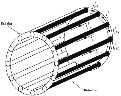
Fig. 5 shows a structure of squirrel cage rotor in an induction machine. The rotor topology has
l + 1 mesh, thus we can write l + 1 independent differential equations to describe electrical dynamic of rotor variables. Suppose, the rotor rings segments have a symmetrical structure,
thus number of l independent equations will be enough for modelling of the rotor dynamics.
According to Fig. 1, jth tooth of rotor is surrounded by jth and ( j + 1) th rotor bars. Thus, based on currents directions of bars and ring segments which are shown in the Fig. 4; the voltage
equation in this loop can be given by:
d φrt = − 2 ir
− ib + ib
dt j
j+1 rrj+1
j rbj
j+1 rbj+1
(57)
This relation can be rearranged in the matrix form and the electrical differential equations for
the rotor cage can be obtained as
d Ψ
dt rt = − 2J rR ri r − A rytR bi b (58)
where the vector i r ∈ R l× 1, R b ∈ R l×l and R r ∈ R l×l denote ring segment currents, rotor bar and ring segment resistance matrices, receptively. These vectors are given by:
T
i r =
ir
ir
· · · ir
(59)
1
2
l
R r = diag rr
rr
· · · rr
(60)
1
2
l
R b = diag rb
rb
· · · rb
(61)
1
2
l


Magnetic Reluctance Method for Dynamical Modeling of Squirrel Cage Induction Machines
53
Also, constant matrix J r ∈ R l×l is defined as
⎡
⎤
0
1
0
· · · 0 0
⎢
⎢ 0 0 1 · · · 0 0 ⎥
⎢
⎥
⎢ 0 0 0 · · · 0 0 ⎥
⎥
J r = ⎢
⎢ .
.
.
.
.
. ⎥
(62)
⎢ ..
.. ..
. .
.. .. ⎥
⎣
⎥
0
0
0
· · · 0 1 ⎦
1
0
0
· · · 0 0
Moreover, there are two current vectors in left hand side of Eq. (58) which have to find a
relation between them. For this propose, Kirchhoff’s Current Law ( KCL) can be used to
determined a relation between rotor bars and ring segments currents. By applying KCL to
jth node (bar) in the rotor cage (Fig. 4), we can write:
ib =
−
j
irj+1 irj
(63)
Therefore, for l nodes in the rotor cage; Eq. (63) can be expressed in matrix form as:
i b = A ryti r
(64)
By substituting Eqs. (64) into (58), we can get:
d Ψ
dt rt = − 2J rR r + A rytR bA ryt i r (65)
Up to this stage, two separate sets of non-linear equations are derived to established of
algebraical (magnetic) and dynamicalal (electric) models of a squirrel cage induction machine.
By combining of Eqs. (50), (51) and (65), the total algebria-differential equations of the system