circuit of three-phase squirrel-cage induction motors using two-dimensional
finite-elements technique. IEEE Transactions on Energy Conversion, Vol. 17, No. 3,
(Spet. 2002), 363-367
Gautschi W. (1964). Error function and Fresnel integrals, Handbook of Mathematical Functions, NBS
Appl. Math. Series, Vol. 55, U.S. Government Printing Office, Washington, D.C.
Jeong, J. H.; Lee E. W. & Cho, H. K. (2003). Analysis of transient state of the squirrel cage
induction motor by using magnetic equivalent circuit method, Sixth International
Conference on Electrical Machines and Systems, Vol. 2, 720-723, 2003
Jung, J. H.; Lee, J. J. & Kwon, B. H. (2006). Online diagnosis of induction motors using MCSA.
IEEE Transactions on Industry Electronics, Vol. 53, No. 6, (Dec 2006), 1842-1852
Krause, P. C.; Wasynczuk, O. & Sudhoff, S. D. (2002). Analysis of Electric Machinery and Drive
Systems (2nd Edition), Wiley-IEEE Press, ISBN 047114326X, New York.
Luos, X.; Liao, Y.; Toliyaty, H.; El-Antably, A. & Lipos, T. A. (1995). Multiple coupled circuit
modeling of induction machines. IEEE Transactions on Industry Applications, Vol. 31,
No.2, (Mar./Apr. 1995), 311-318
Mirafzal, B.& Demerdash, N. A. O. (2004). Induction machine broken-bar fault diagnosis
using the rotor magnetic field space-vector orientation. IEEE Transactions on Industry
Applications, Vol. 40, No. 2, (Mar./Apr. 2004), 534-542
Mirafzal, B.& Demerdash, N. A. O. (2008). Induction machine broken bar and stator
short-circuit fault diagnostics based on three-phase stator current envelopes. IEEE
Transactions on Industry Applications, Vol. 55, No. 3, (March 2008), 1310-1318
Muñoz, A. R. & Lipo, T. A. (1999). Complex vector model of the squirrel-cage induction
machine including instantaneous rotor bar currents. IEEE Transactions on Industry
Applications, Vol. 35, No. 6, (Nov./Dec. 1999), 1332-1340
Ostovic, V. (1989). A novel method for evaluation of transient states in saturated electric
machine. IEEE Transactions on Industry Applications, Vol. 25, No. 1, (Feb. 1989), 96-1000
Ostovic, V. (1989). Dynamics of Saturated Machines, Springer-Verlag, ISBN 0387970797, New
York
Siddique, A.; Yadava, G. S. & Singh, B. (2005). A review of stator fault monitoring techniques
of induction motors. IEEE Transactions on Energy Conversion, Vol. 20, No. 1, (March
2005), 106-114
Sprooten, J. (2007). Finite element and electrical circuit modeling of faulty induction machines study of internal effects and fault detection techniques. Ph.D. thesis, Department of Bio, Electro
and Mechanical Systems (BEAMS), University Libre de Bruxelles
60
Electric Machines and Drives
Su, H. & Chong, K. T. (2007). Induction machine condition monitoring using neural network
modelling. IEEE Transactions on Industry Applications, Vol. 54, No. 1, (Feb. 2007),
241-249
4
Minimization of Losses in Converter-
Fed Induction Motors – Optimal Flux Solution
Waldiberto de Lima Pires, Hugo Gustavo Gomez Mello,
Sebastião Lauro Nau and Alexandre Postól Sobrinho
WEG Equipamentos Eletricos S.A. – Motores
Research and Development of Product Department
Av. Pref. Waldemar Grubba, 3000 – malote 41
Jaraguá do Sul, SC - 89256-900
Brazil
1. Introduction
When a TEFC induction motor fed by static frequency converter drives a load which
demands constant torque throughout the operation range, the low speeds are thermally
critical, because the motor losses (heat sources) do not vary much as a function of the speed,
but the ventilation efficiency decreases as the operation speed falls down, since the fan is
installed on the very motor shaft. In such cases, when operating at low speeds, the
temperature rise often exceeds the limits of the motor thermal class due to the lack of
cooling. In order to prevent this problem the industry has traditionally adopted one of the
following solutions: independent ventilation (a small auxiliary motor is used to exclusively
drive the fan that provides the main motor cooling) or oversizing (the motor used in the
application provides a higher torque than the rated load demand). However, neither one
nor the other of these two options are attractive, as both, besides increasing the space
required for the installation, still increase the motor price [1].
Frequency converters usually apply to the motor a constant voltage/frequency ratio
throughout the operation range, so that no loss control is provided. But the study on the
motor losses composition and its relation with voltage, frequency, magnetic flux and
current, allied with the study on the influence of the ventilation on the temperature rise of
the motor, has led to an optimal voltage/frequency ratio, which minimizes the total motor
losses at each speed [2]. This way, by implementing the automatic control of the
voltage/frequency ratio in the converter, the motor loss minimization can be automatically
obtained throughout the frequency range, so that the motor temperature rise is kept within
the thermal class limits even at low speeds with reduced ventilation.
2. Determination of losses
The fast growth of the number of industrial applications using static frequency converters
recently observed in variable speed drives has encouraged the meticulous study of losses in
magnetic materials under PWM supply by several researchers [3, 4, 5, 6, 7, 8]. They have
62
Electric Machines and Drives
shown that such losses depend on a number of control parameters, such as the modulation
index, the number of levels and pulses of the frequency converter and the duration of PWM
signal pulses. On the other hand, Boglietti et alli have concluded that the flux waveforms
resulting from PWM supply differ from those resulting from sinusoidal supply just except
for a small ripple, which depends on the switching frequency, and that above approximately
5 kHz the iron losses can be considered independent of this parameter [9]. Such studies
represent the first step towards the understanding of the losses behavior in electric motors
under PWM supply, that involves a higher degree of complexity and is not restricted
exclusively to the magnetic materials issue, but includes also additional losses in the
conductors and due to the cooling system and depends, besides the control parameters, on
some machine design parameters, such as the flux density, the lamination geometry and the
connection of windings [3, 10, 11, 12], as well as on other variables inherent to the
manufacturing process [13].
For the purposes of this study, however, the analysis of the motor losses can be simplified,
so that it is enough to separate the total motor losses in three key components:
P = Pfe + Pj + Pmec (1)
where:
Pfe – Iron losses, which depend on the flux density (or magnetic induction), the frequency
and the quality of the magnetic material.
Pj – Losses by Joule effect, which depend on the currents flowing through the stator
windings and the rotor bars.
Pmec – Mechanical losses due to cooling system (fan coupled to the shaft) and friction,
which depend on the speed.
The iron losses are classically considered as being composed of two portions: Hysteresis losses
(pH) and induced eddy current (Foucault) losses (pF). For a lamination sample tested in
Epstein Frame with sinusoidal supply, the hysteresis losses are directly proportional to the
frequency ( f) and to the square of the magnetic induction ( B2), while the eddy current losses are proportional to the square of both the frequency ( f2) and the magnetic induction ( B2), especially for induction values above one Tesla (1 T). However, in the induction motor the iron
losses present a much more induction-dependent behavior than the quadratic ratio obtained
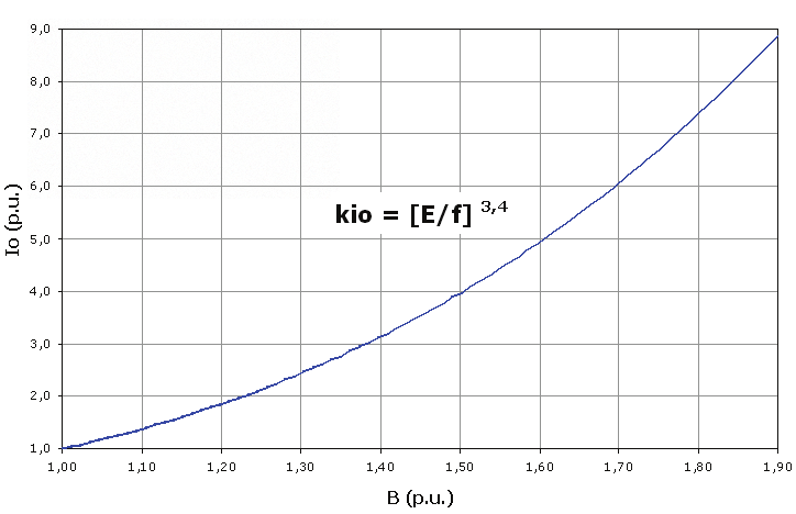
with normalized samples of the magnetic material in Epstein Frame tests. In low-voltage three-
phase induction motors manufactured with fully processed steel laminations tested under
different saturation levels, iron losses presented a dependance on the induction close to B4 for
inductions above 1,2 T (usual value for industrial motors), as presented in Fig. 1.
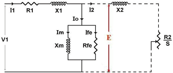
The fundamental theory of the electric machines shows that the torque provided by the
induction motor is directly proportional to the product between the magnetic flux and the
electric current [14, 15]. Then in order to keep a constant torque, if the flux increases the
current can decrease (and vice-versa). As the Joule losses are directly proportional to the
square of the current, these losses can be considered as inversely proportional to the square
of the magnetic flux. From the Faraday-Lenz law of induction, one can easily demonstrate
that the magnetic flux in the motor is directly proportional to the ratio between the
electromotive force ( E) and the frequency. Considering the steady-state model of equivalent
circuit of the induction motor per-phase (Fig. 2), it can be noted that at the base frequency
the voltage drop in the primary impedance has little significance, so that the flux can be
considered as proportional to the V1/f (voltage/frequency) ratio.
Minimization of Losses in Converter-Fed Induction Motors – Optimal Flux Solution
63
3,25
Motor 30kW IV poles 400V 50Hz
3,00
2,75
2,50
.).u 2,25
p
pfe = (E/f)4
(e 2,00
pf 1,75
1,50
1,25
1,00
1,00
1,05
1,10
1,15
1,20
1,25
1,30
E/f (p.u.)
Fig. 1. Iron losses x Magnetic induction for an industrial three-phase induction motor
Fig. 2. Steady state equivalent circuit of the induction motor per-phase
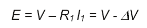
For low operating frequencies, however, in which the input voltage is reduced, the voltage
drop in the primary resistance becomes important and can be no longer despised. By
neglecting the influence of the primary reactance, electromotive force E is given by
(2)
The voltage drop at the stator branch (Δ V) then depends directly on the stator current ( I1).
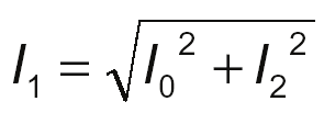
As Fig. 2 shows, the motor current can be decomposed into two components: one
concerning magnetization and the other concerning torque production.
(3)
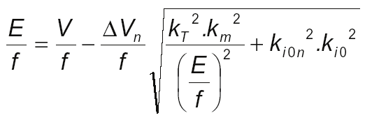
Taking rated voltage as the base, E/f ratio per unit can be written as:
64
Electric Machines and Drives
(4)
where:
Δ Vn - Voltage drop per unit with rated frequency and load.
f – Motor operating frequency per unit, considering rated frequency fn as the base.
In (4), the square root results in a correction factor, which is function of the motor current
and whose terms are explained in the following paragraphs.
It should be taken into account that, as the frequency (and consequently, the rotation) is
reduced, the mechanical losses decrease in a nearly cubic proportion to it ( f3). The
mechanical losses do not affect the iron losses, but they act as an additional load to the
motor, therefore they must be considered as a torque to be added to the rated torque
available on the shaft. Its reduction implies current reduction and so reduction of Joule
losses in the conductors ( Pj).
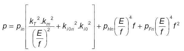
Thus it is possible to rewrite the induction motor total losses per unit p, for operation with variable voltage and frequency, as follows:
(5)
where:
pin – Total Joule losses with the motor operating at rated conditions of load, voltage and
frequency.
pHn – Total hysteresis losses with the motor operating at rated conditions of load, voltage
and frequency.
pFn – Total eddy current losses with the motor operating at rated conditions of load, voltage
and frequency.
Motors manufactured with low loss magnetic core (fully processed silicon steel) operating at
rated conditions typically present values of 80%, 12% and 8%, for parameters pin, pHn and
pFn, respectively. The remaining parameters of (5) will be opportunely explained ahead.
The term of (5) in brackets refers to the motor Joule losses and depends on the total motor
current. The second and third terms refer to the motor iron losses for hysteresis and eddy
currents, respectively. The magnetic induction was conveniently replaced by the E/f ratio.
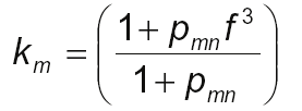
There is no explicit term for the motor total mechanical losses in the equation, because they
are embedded in the first term, in accordance with what was mentioned before, by means of
the factor km defined below:
(6)
where pmn is the mechanical losses at rated speed referred to the rated output power Pn.
The aim of this study is to minimize the motor losses, in order to reduce its temperature rise,
so that the need of both the torque reduction (oversizing) and the use of independent
ventilation can be prevented. In (5), this is considered by means of the derating factor kT,
Minimization of Losses in Converter-Fed Induction Motors – Optimal Flux Solution
65
which will be addressed later on this paper. It should be noted that the torque affects only
the current-dependent losses, not influencing the iron losses. Therefore, km and kT are torque correction factors required to compensate for the effects of the speed variation, which
influences the portion of losses related to the load current.
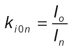
Ki0n is the no-load current factor, defined by (7).
(7)
where:
Io – No-load current under rated voltage and frequency.
In – Full-load current under rated voltage and frequency.
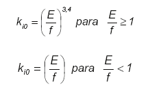
Due to the non-linearity of the magnetization curve of the laminations, the E/f ratio increase
causes the no-load current to increase according to (8). This peculiar behavior of the no-load
current was observed experimentally (Fig. 3), and is taken into account in (5) by means of
the factor ki0.
(8)
Fig. 3. Magnetizing current x E/f
66
Electric Machines and Drives
3. Minimization of losses
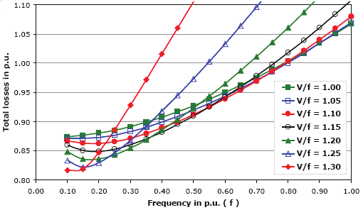
The analysis of (5) shows that the induction motor global losses depend on both the
operation frequency and the induction (or magnetic flux). Then the values of V/f that
minimize the motor global losses change with the operation frequency, so that it is necessary
to find the minimum losses at each frequency, with different values of V/f. Fig. 4 shows the
total losses calculated as function of the frequency for various values of the V/f ratio.
Fig. 4. Total losses x frequency curve for several V/f ratios at rated torque
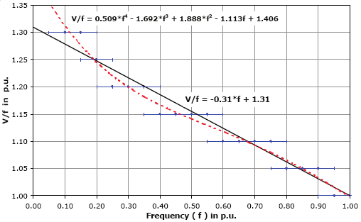
Fig. 5 derives from the family of curves above and represents the V/f ratios theoretically
obtained, which minimize the total losses of the motor at each operation frequency.
Fig. 5. V/f x frequency curve for minimization of total losses
Minimization of Losses in Converter-Fed Induction Motors – Optimal Flux Solution
67
4. Influence of ventilation reduction
Thermal calculations implemented for a number of motors of distinct frame sizes and power
ratings considering speed variation, combined with experiments and tests performed with
several motors at rated load, varying separately the fan speed from zero to base speed, led
to the conclusion that TEFC three-phase motors of a wide output range present a similar
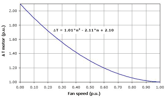
thermal behavior. Fig. 6 represents the temperature rise per unit of low-voltage 4-pole cage
induction motors manufactured with die cast iron frame as a function of the fan speed per
unit.
Fig. 6. Temperature rise x fan speed at rated load
In this approach, for each desired value of frequency and for each value of V/f ratio
according to Fig. 5, the total losses p are calculated according to (5). Fig. 6 determines the
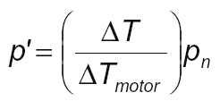
influence of the ventilation reduction on the motor temperature rise (Δ Tmotor). So in order for the required motor temperature rise to be assured, it is necessary to calculate a new
value of p, henceforth referred to as p’, according to (9).
(9)
where:
p’ – total motor losses for the required temperature rise, considering the ventilation
reduction.
pn - total motor losses at rated conditions.
If, for instance, the maximum required temperature rise is the limit of the insulation system
thermal class, then Δ T = Δ Tclass. If, otherwise, the maximum required temperature rise is
Δ Tn, then Δ T=1.
68
Electric Machines and Drives
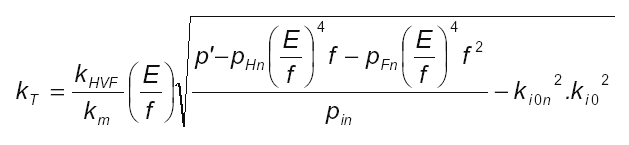
Once known the total losses p’ that will cause the required temperature rise in the motor with
reduced ventilation, then it is possible to calculate the convenient derating factor using (10):
(10)
where kHVF is the harmonic voltage factor as defined by NEMA [16]. It was placed in the
equation originally conceived as (5) for the influence of the PWM supply voltage harmonics
to be also considered on the motor temperature rise. For most of the modern static
frequency converters kHVF is 0.95.
As a consequence of the cooling reduction, kT is usually lower than 1. However, if the
minimized total losses are such that reduce the motor temperature rise even with poor
ventilation, kT can be higher than 1. Similarly, if kT is calculated for an insulation class temperature rise, it will be normally higher than 1 if the rated motor temperature rise is
much below the insulation class temperature rise limit.
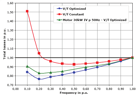
Fig. 7 presents an example of loss reduction achieved with the proposed method. A three-
phase, 30 kW, 4-pole induction motor was tested at constant rated torque within the
frequency range from 0.1 to 1.0 (p.u.). The results are presented for three different situations:
calculation with constant flux, calculation with optimal flux and testing with optimal flux.
The loss reduction obtained with the proposed technique, as shown in Fig. 7, results in a
better thermal performance of the motors operating with optimal flux. Comparing the motor
temperature rises when operating at constant flux condition to those when operating at
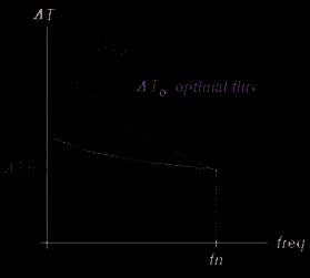
optimal flux condition, it is remarkable a behavior similar to that outlined in Fig. 8, as can be
checked in the experimental results presented in section VI.
Fig. 7. Total losses (p.u.) x frequency (p.u.)
Minimization of Losses in Converter-Fed Induction Motors – Optimal Flux Solution
69
ΔTn: temperature of thermal stabilization of the motor fed by sinusoidal supply (mains)
ΔT0: temperature of thermal stabilization of the motor fed by converter supply
fn: operation base frequency of the motor
Fig. 8. Temperature rise x operation frequency, sketch of the motor performance under
different flux conditions
5. Validation and implementation of the optimal flux curve
To validate the proposed technique, temperature rise tests with speed/ventilation variation
were accomplished for a wide range of industrial motor ratings. This way, it was possible to
compare the thermal performances of converter-fed motors when under constant flux (rated
losses) and optimal flux (minimum losses) conditions.
Before the implementation of the automatic function for optimal flux selection by the
converter, drives with suitably modified softwares were used, so that specific flux values
could be manually adjusted. This allowed the practical correction of the curve obtained by
means of mathematical calculations and the finding of the actual optimal flux curve that was
implemented in the converters used in the tests, into which were incorporated the automatic
function for the optimal flux setting.
As the sensorless vector control enables the magnetic flux of the motor to be directly altered,
this was the control type employed in all tests with converter. The switching frequency used
in all tests with converter was 2.5 kHz.
A. NEMA High Efficiency (NHE) Motors
The motors to be tested were selected considering the worst horsepower/frame size ratios
criteria. The following machines were used in the tests, all of them 4-pole (predominant
polarity in low-voltage industrial applications) and all of them with class F insulation: 5 hp
(NEMA 184T); 20 hp (NEMA 256T); 50 hp (NEMA 326T) and 150 hp (NEMA 444T).
Occasionally, for investigation of specific issues, tests were also realized with motors that
are not related above.
70
Electric Machines and Drives
It should be noted that the loss minimization technique was conceived and devel