In the field, you can test the filtration properties and filter-cake thickness using the filter-press kit. This kit consists of a press with a mounted pressure gauge and a CO charging system that is 2
used to simulate the hydrostatic pressure inside a 200-foot hole. By placing a sample of drilling mud in the press and charging the system, you can forma filter cake. The filter cake should be less than 2/32-inch thick.
(7) Salty Environment. A high chloride content in the mixing water causes bentonite to react anomalously or not react at all. The ground bentonite remains agitated; it does not disperse, hydrate, or swell. In salt water, bentonite is an inefficient clay additive for drilling mud. The dissolved salt is an electrolyte that changes the interparticle activity of bentonite. If you add sufficient amounts of salt water to a fresh water and bentonite mud mixture, the dispersed platelets will form lumps.
Viscosity and filtrate loss increase and the mud’s ability to build a thin, impermeable filter cake decreases.
Attapulgite is often used for salty formations.
The small particles produce a high
surface-area-to-volume relationship and good viscosity building. Unlike bentonite, the particle shape is needle-like. Viscosity building in attapulgite depends on the entanglement of these needles.
The disorderly arrangement of the particles accounts for the poor filtration qualities of attapulgite.
The filter cake is more like a layer of strew or sticks. Attapulgite clay does not have the physical qualities to build a thin, impermeable filter cake. If you can mix bentonite in fresh water first and then add salt water as make-up water, the bentonite flocculates; that flocculation can be reversed by chemical treatment.
(8) Well Hydraulics. You must have a basic understanding of well hydraulics. Fluid is pumped down the drill string, out the ports in the bit, and up the annular space between the drill string and the wall. The fluid empties into the mud pit, through any mechanical solids separating equipment, and is picked up from the pit by the mud pump for recirculation. The system is intended as a conservation system. Except for mud lost into the formation or where artisan water exceeding hydrostatic pressure flows into the hole, the return is largely complete and the mud-pit level does not change. Even if thes system is in equilibrium, you need to understand the up-hole rearrangement of flow patterns.
Fluids flow in two distinct patterns. Laminar flow is orderly. The streamlines remain distinct and the flow direction at every point remains unchanged with time. Turbulent flow is disorderly.
The flow lines and directions are confined and heterogeneously mixed. The type of flow depends on the cross-sectional area of the fluid course and the velocity, density, and viscosity of the fluid.
In water-well drilling, the cross-sectional area of the annulus is usually several times that of the inside diameter of the drill string. Because of the increase in volume in the annular space, flow at the point the fluid leaves the bit is turbulent. The fluid becomes laminar flow when it begins flowing up the annular space. The returning fluid velocity is slower and the drill fluid is more dense and probably has more apparent viscosity, which affects the flow pattern. To clean the hole and carry the drill cuttings out, turbulent flow in the annulus would be better.
5-17
FM 5-484/NAVFAC P-1065/AFMAN 32-1072
Picture the flow in the annulus as a series of nested tubes. Velocity varies as if these tubes were sliding past one another while moving in the same direction. Flow near the wall and near the drill string is at a slower rate than near the center. Cuttings near the center can be vigorously lifted while cuttings near the wall and drill string actually slip in a net fall. Rotation of the drill string changes the flow pattern near the drill string and materially enhances particle lift.
For example, if you use a 3 1/2-inch ID and 4-inch outside diameter (OD) pipe to drill a 9-inch hole and pump 200 GPM, the velocity of the ID pipe is 400 feet per minute (fpm) and the velocity of the OD pipe is 75 fpm. To test cumulation at these rates (bit is 300 feet deep), pump down a marker (strew or oats). The majority of the material should take 4 minutes and 45 seconds to return (300 feet at 400 fpm takes 45 seconds and 300 feet at 75 fpm takes 4 minutes). To clean all the cuttings from a 300-foot depth with an average up-hole mud velocity of 75 fpm will require more than four minutes of pumping. Consider this concept regarding sampling cuttings from the return mud.
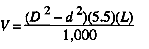
If cuttings remain in the annular space between the drill rod and borehole wall when circulation is stopped, they will produce a denser fluid than the clean drilling mud inside the drill rods. The denser mud in the annular space will then flow down the hole and force the clean drilling mud up the drill rods. This causes a geyser effect, and the drilling mud may shoot several feet into the air until the mud columns equalize. (Some drillers mistake this for a caving hole.) If this situation happens when adding drill rods, the circulation time should be increased after drilling down the next rod. Use the following formula to calculate the annular space volume where—
V = annular space volume, in cubic feet.
D = hole diameter or bit size, in inches (Figure 5-4, page 5-8)
d = drill hole or drill steel collar diameter, in inches (Figure 5-4, page 5-8)
L = hole length, in feet (Figure 5-4, page 5-8)
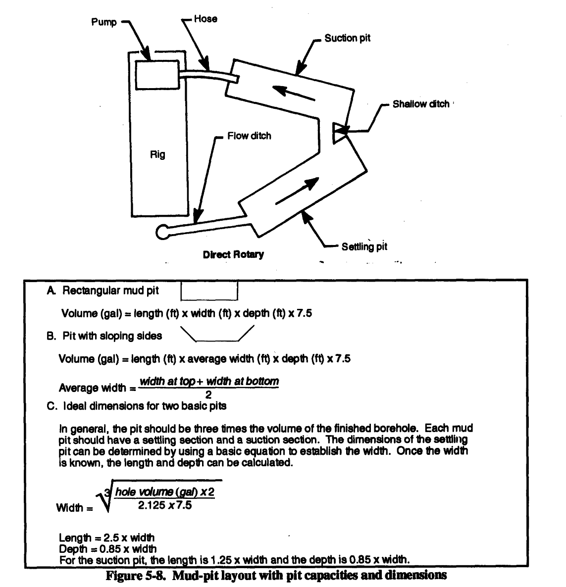
(9) Mud Pits. Rotary chilling preparation is the design and excavation of an in-ground mud pit or installation of a portable mud pit and the mixing of the drilling fluid. For standard drilling operations that use well-completion kits, well depths could range from 600 to 1,500 feet. For wells up to 600 feet using the 600-foot WDS, use portable mud pits. For wells over 600 feet, use dug mud pits. In either case, you will have to clean cuttings from the pits as drilling progresses. Design considerations include the anticipated depth and diameter of the drill hole, since the material cuttings from the hole will be deposited in the mud pits.
The volume of the pits must equal the volume of the completed hole. Therefore, during drilling, you will have to clean the cuttings from the pits frequently. If you have a backhoe to dig and clean the pits, size and depth of the pits are not critical. If you must dig and clean the pits with shovels, width and depth are important. Drilled cuttings should drop out of suspension in the mud pit.
Therefore, long, narrow pits are better. Figure 5-8 shows a mud-pit layout and a chart depicting
mud pit capacities and dimensions.
NOTE: Portable mud pits will require constant cleaning.
5-18
FM 5-484/NAVFAC P-1065/AFMAN 32-1072
Mud pits are part of the circulating system for mixing and storing drilling fluid and for settling cuttings. The ground slope will affect site layout. Pit design can enhance pit performance. Most drillers agree&t using multiple pits is best when dropping drill cuttings from the fluid. The volume of the pit should be one and one-half to three times the volume of the hole. This will provide fluid to fill the hole and an excess volume to allow stilling and settlement or processing before returning to the drill string. A volume of three times the hole volume will minimize drilling-fluid and mud-pit
maintenance. Figure 5-9 (page 5-20) shows a mud pit that is prepared on-site. Figure 5-10 (page
5-20) shows a portable mud pit.
5-19

FM 5-484/NAVFAC P-1065/AFMAN 32-1072
5-20


FM 5-484/NAVFAC P-1065/AFMAN 32-1072
If drilling mud is processed through shale shakers, desanders, desilters, and space and time for cuttings settlement are not important, long, narrow pits connected at opposite ends by narrow, shallow trenches are preferred. If using a polymer fluid that has no thixotropic qualities, the settlement of cuttings is a function of time at low velocity or no flow. With polymer fluid, a long-path mud pit is ideal; if part of the flow almost stops, cutting settlement is enhanced.
If you use a clay-based mud with thixotropic qualities and the mud moves slowly or flow stops, the gel strength can hold the cuttings. High velocity through narrow, shallow trenches holds the cuttings in suspension. If mud runs over one or more wide baffles or weirs, flow shear and velocity are low. These factors enhance cuttings to drop out. If mud processing equipment is available, use it. Recirculating clean fluid reduces power requirements, wear, and erosion and enhances drilling
rate. See Figure 5-11 and Figure 5-12 (page 5-22) to calculate weir dimensions and volume.
5-21


FM 5-484/NAVFAC P-1065/AFMAN 32-1072
f. Rotary Drilling Problems. Some problems in rotary drilling are minor and others are serious and can result in failure to complete a hole or even loss of equipment. Many serious problems start minor but can become serious if not recognized or handled properly. For example, in a loose sand zone, the borehole walls can slough and cause drilling fluid loss. By reducing or increasing fluid velocity, you can stabilize the wall and regain fluid circulation. However, if you do not recognize the condition and you continue drilling, the wall will slough and create a cavity. The cuttings lose velocity, become suspended in the cavity, and tend to fall back into the hole when you add a rod.
This action can result in the rods or the bit becoming stuck in the hole. Other problems can result from subtle changes in geology, imbalances in the drilling operation, or equipment failure.
5-22

FM 5-484/NAVFAC P-1065/AFMAN 32-1072
(1) Lost Circulation. Lost circulation refers to a loss in volume of drilling fluid returning to the surface. The implication is that some fluid pumped down the drill pipe is entering the formations.
The mud pit will lower, since some of the mud is used in forming a mud cake on the borehole wall; however, increased lowering can indicate circulation loss. Losses can occur through open-graded sand or gravel or open joints in rock. A loss can occur when cuttings are not washed out and the borehole annulus becomes restricted, resulting in increased down-hole pressure. Spudding (raising and lowering the drill string) the hole too violently can cause loss. Spudding helps wash cuttings, but down-hole pressures increase momentarily. Experienced drillers can estimate when spudding is safe. When fluid cumulation is lost and a driller continues to drill, he is drilling blind. An experienced driller that knows the rig can often drill blind successfully, but reestablishing circulation is always safer.
Reestablishing circulation can involve several techniques. You can add commercial items such as chopped paper, straw, cottonseed, and nut hulls to the mud pit. Sometimes, while the loss zone is grouted and redrilled, the grout is lost into the formation. In this situation, you may have to set casing through the loss zone. Occasionally, reducing fluid velocity while continuing to drill will plug the loss zone with drill cuttings. Reestablishing circulation is usually a trial-and-error process.
The longer you drill without circulation the more difficult it will be to reestablish circulation.
(2) Fall-In. Fall-in is material that accumulates in the bottom of the borehole after you stop cumulation. This material is borehole-wall material that results from sloughing or caving or cuttings previously carried in suspension. Fall-in occurs when you encounter a loose, unstable formation and the drilling-fluid weight is insufficient to stabilize the formation. If you anticipate or suspect fall-in, raise the drill bit off the bottom of the hole (20-foot minimum) each time drilling is interrupted. This will prevent the cuttings and fall-in from settling back around the bit until the problem is solved.
(3) Stuck Drill String. The drill bit and any collars just above the bit are larger in diameter than the drill pipe. The string becomes stuck when cuttings collect on the bit and collar shoulder.
This condition is called sanded in. Be careful because you can break the drill pipe while trying to remove the drill string. Regaining circulation and working the sand out are seldom successful. If the formation will not take the fluid when you engage the pump clutch, the relief (pop-off) valve will operate to relieve the pressure. Little can be done to free the drill string except to wash a small pipe down the annulus to the bit and jet the settled sand back into suspension. When the annulus is too small to pass a jet pipe, a part of the drill string may be lost.
When the annulus is small, excessive up-hole velocity can promote erosion of the filter cake in granular zones and allow caving against the drill pipe. If this occurs, try to maintain circulation and rotation, even if circulation is slight. Where the grains are angular, the drill pipe can become locked while being rotated. This situation is similar to a sanded-in bit. With smooth pipe (not upset), hammering up and down will sometimes dislodge the string. You can reestablish circulation 5-23
FM 5-484/NAVFAC P-1065/AFMAN 32-1072
and continue drilling. Be careful because hammering up and down can produce unfavorable compacting of the sand. In a hole of fine-grained soil or shale, where the alignment has significantly deviated and the drill pipe has wallowed into the wall, the pipe can become wall stuck. Pipe friction and relatively high borehole pressure can move the pipe tighter into the wallowed groove as you pull the string. An alert driller should recognize early stages of deviation and take measures to realign the hole.
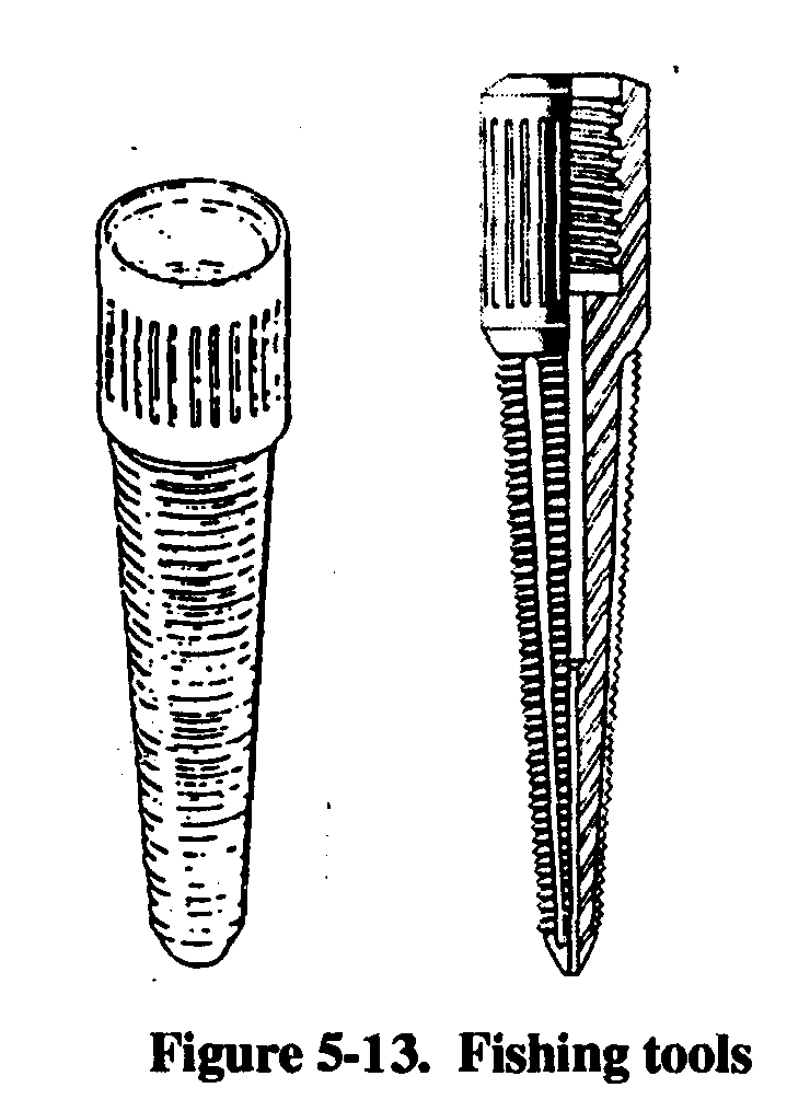
(4) String Failure. When the drill string parts, leaving a portion in the borehole, the drill string is rung off. The portion in the borehole is a fish and attempts to retrieve the portion is fishing.
Fishing tools include a tapered tap and an overshot die (Figure 5-13). Ringing off is normally fatigue failure in the drill-rod joints caused by excessive torque or thrust (repeated flexing and vibration that crystallizes heat-treated tool joints) or by borehole deviation (with flexing of the string).
Examine drill rods for signs of failure.
(5) Deviation. A deviated borehole is called going
crooked. If you make the initial setup without plumbing the kelly, you can expect the borehole to go crooked. A crooked
borehole usually amplifies other problems and can make a
borehole unsuitable for a well. You should always anticipate deviation, since the borehole naturally tends to spiral from bit rotation. Variations in the formation badness may start
deviation. Excessive bit load magnifies minor initial
deviation. Use all available guides and collars and a
reduction in bit load to minimize deviation.
(6) Swelling Soil. The in-hole effects of swelling soil
(shale or clay) that absorbs water from the drilling fluid is squeezing. The result is a borehole that is undergauged to the extent that you cannot pull the bit by normal hoisting
methods. In such cases, you can cut back through the
blockage with a roller rock-bit or a drag bit. Swelling can
cause caving and failure of the wall. Keep water out of the
formation to prevent swelling. Special polymer drilling fluid additives that limit water absorption are available. High quality bentonite forms a thin but highly impermeable filter cake.
5-2. Air Rotary Drilling. Air rotary drilling is similar to mud rotary drilling except that the fluid circulated is compressed air. The air is not recirculated. Using compressed air is advantageous when water for drilling is inconvenient, fluid is being lost to the formation while drilling, or you have difficulty washing sticky clay formations from the hole. Also, air rotary drilling requires much less development time. You may have to adjust air rotary techniques with each well you drill. Some disadvantages to air rotary drilling are that air cannot support the wall of a hole in an unstable formation, changes in the return air flow are not as readily apparent as in mud flow, and air is not as effective in cooling and lubricating the drill bit and string.
a. Air Supply. Air has no density or viscosity, so cuttings are blown out of the hole at high velocity. The up-hole air flow is turbulent and more effective in lifting the cuttings. The lack of density and viscosity increases the particle slip so a continuous and high velocity up-hole flow must be maintained to keep the hole clean. An upward velocity of about 4,000 fpm is sufficient to clean 5-24

FM 5-484/NAVFAC P-1065/AFMAN 32-1072
cuttings out of the hole. Cutting removal also depends somewhat on size, density, and amount of cuttings. Up-hole air velocity is computed by dividing the output volume of the air compressor, in cfm, by the cross-sectional area of the annulus of the hole, in feet. Air compressors are rated on the following items:
Intake air volume.
Condition. Compressors wear with use, causing capacity to decrease.
Sea level. Output volume capacity is reduced about 3.5 percent for every 1,000 feet above sea level.
Temperature. Efficiency is reduced when temperatures are above 60°F and is increased when temperatures are below 60°F.
Rotation speed. Output from the compressor is directly proportional to the motor’s RPM.
Do not operate a compressor at lower RPM to reduce wear.
Dry material drilled by air will create a large amount of dust when blown from the borehole.
Inject water to control the dust. Depending on the nature of the material drilled, the amount of water could be 1/2 to 5 GPM. Water injection increases air density and improves carrying efficiency for the cuttings. Adversely, water can cause the cuttings to stick together, making them heavier and harder to blow out of the borehole, or the cuttings may stick to the borehole wall, causing constriction.
Minor wetting or dampening makes some walls more stable; excessive wetting can cause a wall to fail. Adjusting the amount of water injected into the borehole takes experience. Air has no wall-stabilizing qualities. In soils where sloughing and caving are a problem, injection of a thin drilling mud (bentonite mixed with the injection water) will control the dust and can contribute to stability.
In drilling large diameters (12 inches) with standard drill pipe (3 1/2 inches OD), the annulus equals 0.7 square feet. Using a 1,000-cfm compressor the up-hole velocity would be about 1,400
fpm, which is not enough velocity to remove cuttings. While penetration will progress, the cuttings tend to stay at the bottom of the borehole under the drill bit and are recrushed. These cuttings act as a pad under the teeth of the bit and prevent proper cutting action. The compressor normally cannot drill holes by straight air rotary.
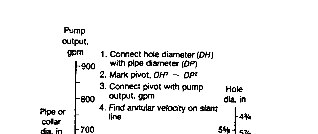
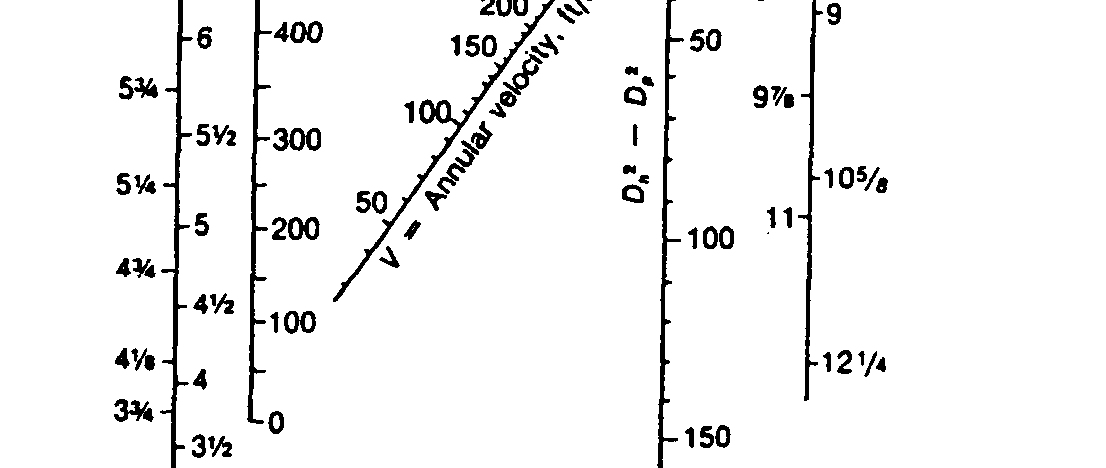
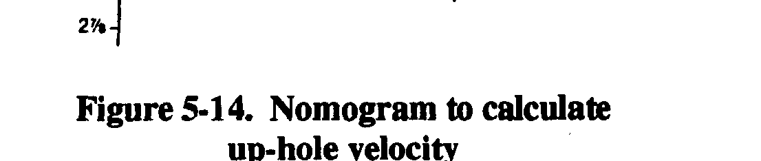
Use the following equations to estimate compressor size, up-hole velocity, and hole-size
requirements for air drilling or Figure 5-14 (page 5-26) to determine up-hole velocity. The
recommended up-hole velocities are: 3,000 fpm, minimum; 4,000 fpm, fair; and 5,000 fpm, good.
V min= ( D 2- d 2)16.5
where—
Vmin = minimum velocity, in cfm.
D
= hole diameter or bit size, in inches (Figure 5-4, page 5-8).
d
= drill steel or drill collar in diameter in inches (Figure 5-4, page 5-8).
and
5-25


FM 5-484/NAVFAC P-1065/AFMAN 32-1072
where—
V
= actual up-hole velocity, in fpm.
C
= compressor capacity, in cfm.
Vmin
= minimum velociy, in cfm.
Air drilling has a depth limitation because
of water in the borehole. Air pressure must
displace the head of water in the borehole
before it can exit the bit. An advantage is that
when you encounter water, it. will discharge
with the air. As drilling progresses, you can
estimate the amount of inflow to the well.
When calculating the static head of water,
remember that 0.434 psi equals 1 foot of head
or 1 psi equals 2.3 feet of water. For example,
the minimum psi required to overcome a
400-foot static water-level column is 173.6 psi
(400 ft x 4.34 psi= 173.6 psi).
b. Foamers. Commercial foamers for
drilling enhance the air’s ability to carry
cuttings and reduce the velocity required to clean the borehole. The foamer is mixed with the injection water but does not foam with gentle stirring; therefore, pumping is not hindered. Foam must be pumped at a pressure greater than the air-line pressure into which it will be injected. The foaming and mixing with air largely occurs when exiting the drill bit. If air flow is reduced from the volume required for air rotary drilling and the injection rate is tuned to the airflow, the foam
leaves the hole as a slow-moving mass (Figure 5-15). The foam is laden with drill cuttings and the
borehole is effectively cleaned with only 10 percent of the air volume required had foam not been used. You can drill boreholes 2 feet or more in diameter with a well-tuned air-foam operation using
air compressors. See Table 5-7 for a list of common problems with air-foam systems.
Commercial foamers vary and come with mixing instructions on the container. You may need only a few foamers to produce large volumes of rich foam. Less than one quart of foamer mixed with 100 gallons of water injected at a 2- to 3-GPM rate is sufficient for a 12-inch diameter borehole.
The column of foam provides slight stabilization to the wall. You can increase the richness and density of the foam by mixing bentonite with the injection water before adding the foamer. A very thin fluid of 15 to 20 pounds of bentonite mixed in 100 gallons of water is suitable for injection in air-foam drilling.
Adding foamer to this fluid in the same proportions as clear water, results in richer, more stable foam. This technique is sometimes called air-foam-gel drilling. The gel refers to the bentonite fraction. Because of the increased richness, stability, and density of the air-foam gel, the air’s cutting-carrying capacity and the wall stabilization are enhanced. Foam reaching the surface must be carried away from the drill rig to avoid mounding over the work area. Foam eventually dissipates 5-26