FM 5-484/NAVFAC P-1065/AFMAN 32-1072
Step 2. Assemble the bail-down
shoe, special nipple, and special
coupling in the bottom of the screen.
Step 3. Screw a length of
premeasured pipe into the right-hand
half of the special coupling. This
pipe, which will extend up through
the screen, is called the bailing pipe
or conductor pipe.
Step 4. Screw one or more packers
to the top of the screen.
Step 5. Lift the whole assembly by
the bailing pipe and lower the screen
inside the well casing. Add lengths
of bailing pipe as the screen descends
until it reaches the bottom of the
borehole.
Step 6. Mark off the length of the screen on the bailing pipe that projects above the casing, using the top of the casing as the reference measuring point. Run a bailer or sand pump inside the bailing pipe and start bailing sand from below the shoe.
6-14


FM 5-484/NAVFAC P-1065/AFMAN 32-1072
Step 7. As you remove sand from below the shoe by the bailer, the combined weight of the screen and the string of bailing pipe will cause the screen to move downward. Attach additional weights to the bailing pipe, if necessary.
Step 8. Monitor the progress of the work carefully, and stop the operation when the screen reaches the desired depth. The packer should be near the lower end of the casing, but still inside the casing. Accurate measurements will avoid sinking the screen too far.
Step 9. Drop a weighted and tapered wooden plug (Figure 6-11 ) through the bailing pipe
to plug the special nipple on the bail-down shoe. When the plug is in place, unscrew the left-hand threaded joint at the upper end of the nipple by turning the entire string of bailing pipe to the right. Remove the bailing pipe and proceed with well development.
If you use a different type of bail-down shoe, the left-hand threaded connection for the bailing pipe may be in the opening in the shoe or it may be in the packer fitting at the top of the screen. In either case, use the same procedures as above for operating the bailing down, plugging the bottom, and removing the bailing pipe.
Under certain conditions, you can bail down a well screen without using a bail-down shoe. The bailing pipe is not connected to the screen. You fit the pipe’s lower end with a flange or coupling large enough to press on the packer at the top of the screen. The weight of the bailing pipe rests on the screen. You fit the lower end of the screen with an open ring or a short piece of pipe. Be very careful when using this method because the screen is not connected to the bailing pipe and you cannot control the screen’s movement from the surface. Careful measurements will prevent sinking the screen too far. This method should be limited to fairly short screens. Plug the bottom of the screen by putting a small bag of dry concrete mix in the bottom and tapping the concrete lightly with the drill bit or other tool.
6-7. Placing Gravel. The most important criteria for grovel pack (artificial sand filters) are comet grain sizes and screen slot opening. Grading should be in proper relation to the grading of the sand in the aquifer. You could have trouble if you use gravel that is too coarse. Coarse, uniformly graded filter sand (about 1/8 inch) makes the best gravel pack for most fine-sand aquifers. You should use fine gravel (1/4-inch maximum size) to pack aquifers consisting of medium or coarse sand. Use a screen with openings that cover about 90 percent of the gravel pack. The following is a field method for producing a filter material or gravel pack from a sand and gravel deposit for a medium sand aquifer.
Make two sieves with lumber. Cover one sieve with 1/4- to 3/8-inch hardware cloth.
Cover the other sieve with window screen.
NOTE: A layer of hardware cloth under the screen provides extra strength to the sieve.
Discard all material that will not go through the hardware cloth but that will go through the window screen. Save the materials that the screen retains for analysis and logging purposes.
a. Open-Hole Placement. Where drilling mud keeps the borehole open, you can install a gravel pack using the positive-placement method. This method is the most common and best suited to military field operations. Use the following procedures for this placement method: Step 1. Drill a large diameter borehole the full depth of the well.
6-15


FM 5-484/NAVFAC P-1065/AFMAN 32-1072
Step 2. Set a smaller diameter screen and casing centered in the large diameter borehole.
NOTE: Basket-type centering guides work best.
Step 3. Fill the annular space around the screen with properly graded gravel.
Step 4. Fill the borehole with gravel well above the top of the screen. Gravel works downward as sand and silt are removed from the formation around the gravel pack by subsequent development.
Development work must be thorough when you drill the borehole using the rotary method because the mud cake on the borehole wall is sandwiched between the gravel pack and the face of the formation. You must break up the mud cake and bring it up through the gravel into the well.
Any mud cake not removed reduces the efficiency and yield of the completed well. To ensure that you remove all of the mud cake, limit the thickness of the gravel envelope around the screen to a few inches. A common mistake is to drill a very large borehole and use a small screen, making the gravel too thick for satisfactory results.
Another common mistake is to try and place gravel pack into a small annular space, such as 1
inch. The gravel pack usually bridges at a coupling and does not get down around the well screen.
A 2-inch annular space is minimum; 3-to 5-inch spaces are best. Remember, the annular space is the difference between the outside of the casing and the wall of the borehole with the casing centered in the hole. In most cases, you must also consider the outside diameter of the couplings.
b. Tremie Placement. You can use a tremie pipe when placing gravel-pack materials. The fine and course particles should not separate, as in the open-hole placement, when the aggregate settles through the drilling fluid in the well. Lower a string of 2-inch (or larger) pipe into the annular space between the inner and outer casings. Feed the gravel into the hopper at the top of the pipe.
Feed water into the pipe with the gravel to avoid bridging the material in the pipe. The pipe raises as the gravel builds up around the well screen. The tremie system is practical for placing the gravel pack in shallow to moderately deep wells.
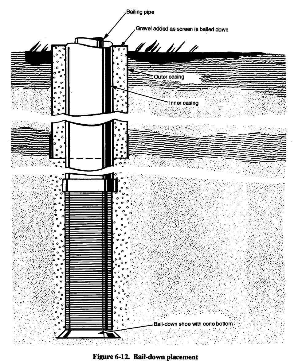
c. Bail-Down Placement. With this method, you can place a gravel pack as you install the screen. Feed the grovel around the screen, it will go downward with the screen. The bail-down shoe used is somewhat larger than the screen so that gravel being added will follow down and around
as the screen sinks in the formation. Figure 6-12 shows this operation. Development work is an
essential part of this method. Screen openings must be larger than the grain size of the aquifer so enough aquifer sand will pass through and the gravel pack will replace the sand around the screen.
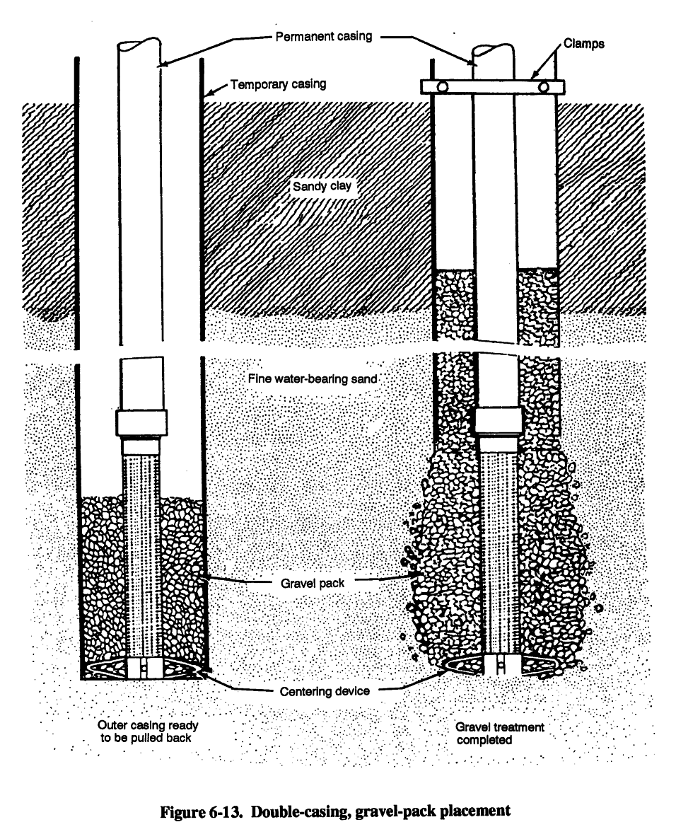
d. Double-Casing Placement. With this method, you place gravel and use a temporary outer
casing (Figure 6-13, page 6-18). With this method, you pull back the casing as you pour gravel into
the space. This method is somewhat similar to pull-back screen installation.
6-8. Using Alternative Methods.
a. Formation Stabilizer. When you do not use a grovel pack you can place formation-stabilizer material to help prevent deterioration of the annular space outside the screen. Fine, loose strata may cave into that space, enter the screened interval, and degrade the well. The decision to use this material usually occurs during the well-construction process. In unstable formations, consider stabilizing wherever the annular space is more than 2 inches thick.
6-16
FM 5-484/NAVFAC P-1065/AFMAN 32-1072
Grain size is important since you will develop the aquifer naturally, and as much as half of the stabilizing material could flow through the screen. The grain size should average slightly coarser than that of the aquifer and should be well distributed. Widely used formation stabilize are 6-16
FM 5-484/NAVFAC P-1065/AFMAN 32-1072
6-18

FM 5-484/NAVFAC P-1065/AFMAN 32-1072
Step 1. Center the screen at its final position in the open section of the borehole, using a centralizer if needed.
Step 2. Place the stabilizer material by dumping and tamping it down the hole or by using a tremie. Raise the level of stabilizing material above the top of the screen and add additional material as development progresses.
Step 3. As you develop the well, the level of the stabilizing material drops as the material is pulled into the screen. You must replace this material to maintain the level above the top of the screen.
b. Unscreened Well. In competent rock, you usually tap the aquifer through numerous, irregularly spaced fractures. Once cleared of mud and rock fragments, the fracture stay open and the intake interval functions efficiently for a longtime. You should not need a screen in such a rock well. If you anticipate an unscreened-well design, you must be particularly attentive to the location of the top of the unscreened intake interval and its relation to the position and thickness of any impermeable layer.
6-19

FM 5-484/NAVFAC P-1065/AFMAN 32-1072
Chapter 7
Well-Completion Procedures
This Chapter implements STANAG 2885 ENGR.
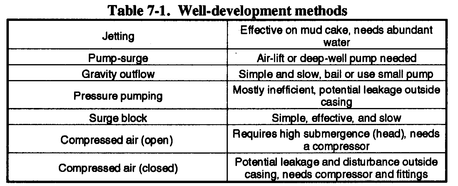
7-1. Well Development. Table 7-1 shows the different well-development methods and some characteristics of each method. All methods are designed to produce a stable flow condition. Be careful not to let the drill strike the bottom plug during well development, especially when using PVC pipe.
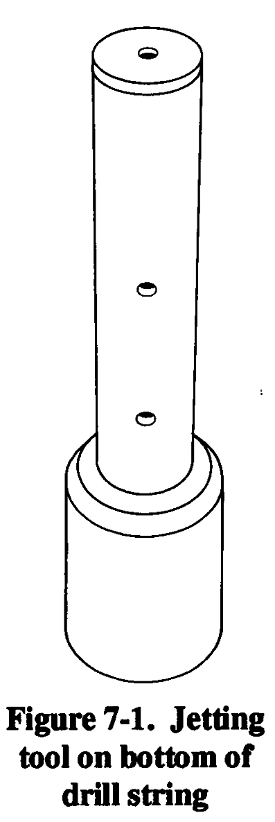
a. Jetting Method. With this method, you use a jetting tool that you lower inside the screen. Use the following procedures for this method: Step 1. Attach the jetting tool (in the well-completion kit) to the bottom of the drill string (Figure 7-l).
Step 2. Use the string to lower this tool into the screen.
Step 3. Connect the upper end of the pipe to the kelly or the discharge side of the mud pump.
Step 4. Pump water into the screen and rotate the jetting tool slowly so that the horizontal jets of water wash out through the screen openings.
Step 5. Raise the string of pipe gradually and continue rotating to backwash the entire surface of the screen. If possible, use a pump pressure of 100 psi.
This backwashing method is effective in removing caked drilling mud from the borehole wall. A disadvantage in military field operations is that this method requires a large supply of water. After covering the entire screen with the jetting tool, remove the tool. Remove the sand that has collected in the sand trap with a bailer. Repeat this process until the well stops producing sand. If a significant volume of material is removed during 7-1


FM 5-484/NAVFAC P-1065/AFMAN 32-1072
development, you should add more filter material around the screen to keep the top of the grovel pack above the top of the screen.
b. Pump-Surge Method. This backwashing technique involves alternately pumping water to the surface and letting the water run back into the well through the pump-column pipe. Use an air-
lift pump or a deep-well turbine pump without a foot valve. See Chapter 4 for discussions on pumps.
Do not use the permanent well pump for development. Pumping sand could damage the pump.
Use the following procedure for this method:
Step 1. Start the pump. As water comes to the surface, stop the pump to release the water. The power unit and starting equipment determine the starting and stopping action of the pump. The effect is to lower and raise the water level in the well intermittently through the screen openings. Periodically, pump the well to remove the sand brought in by surging.
Step 2. Remove the pump and bail out the material in the sand trap, after surging.
Step 3. Repeat the process until the well stops producing sand.
c. Gravity-Outflow Method. Backwashing by gravity outflow involves pouring water into the well rapidly to produce outflow through the screen openings. Inflow through the screen is then produced by bailing water from the well rapidly. This is a slow surging technique requiring several minutes to complete a cycle. If the static water level is high enough to permit pumping b y suction lift, you can use a small centrifugal pump instead of the bailer to speed up the work. If there is room in the well casing, connect the discharge side of the pump to a string of small diameter pipe that is lowered into the well. The water added is pumped down inside the screen, creating a turbulence that will help to develop the formation.
d. Pressure-Pumping Method. Occasionally, wells are backwashes by capping the casing and pumping water into the well under pressure. Water is forced outward through screen openings
similar to the closed-well method of using compressed air for development (paragraph 7-1f(2), page
7-5). Pressure pumping is an inefficient method because the desirable surging effect is difficult to produce. You must make sure to seal the casing tightly in the borehole and prevent water from being forced up around the outside of the casing.
e. Surge-Block Method. With this method, water is surged up and down in the casing with a surge block or plunger. A surge block can be a solid plunger or swab or a plunger equipped with
or without a valve opening (Figure 7-2). The valve-type plunger gives a lighter surging action than
the solid type. Light surging is advantageous in developing tight formations. Therefore, start the surging process slowly and increase the force as the development proceeds. Be careful when working with wells using PVC pipe. The casing or well screen could collapse from vigorous surging action. Plugging the valve of the plunger changes it to a solid-type plunger that you can use when you need greater surging force. Attach sufficient weight to the surge plunger to make it fall with the same speed on the downstroke as the drilling machine uses on the upstroke. The drill stem provides the weight required for the surge block. Use the following procedures for the surge-block method:
Step 1. Lower the surge plunger into the well until it is in the water above the top of the screen. Keep the plunger a few feet above the screen so that it will not strike the screen while surging.
7-2


FM 5-484/NAVFAC P-1065/AFMAN 32-1072
Step 2. Start surging
slowly and gradually
increase the speed until
the surge plunger rises and
falls without slack. With
a rotary rig, lift the plunger
3 or 4 feet before dropping
it. When using the sand
line, control movement by
using the hoist brake and
clutch.
Step 3. Continue surging
for several minutes. Pull
the plunger out of the well
and lower the bailer or
sand pump into the screen.
When the bailer rests on
the sand that has been
pulled into the screen,
check the depth of the
sand by measuring on the
sand line. Bail all the sand
out of the screen.
Step 4. Repeat the surging
operation and compare the
quantity of sand with the
first quantity. Bailout the
sand.
Step 5. Repeat surging and bailing until little or no sand can be pulled into the well.
Lengthen the period of surging as the quantity of sand removed decreases.
f. Compressed-Air Methods. Compressed air provides rapid and effective development of wells, using an open- or closed-well method. You can use the standard 350-cfm compressor for developing most wells at a pressure of at least 100 psi. However, a higher pressure is preferable.
The 250-cfm compressor will pump water by air lift from 100 to 150 GPM, depending on the
submergence and size of the pipes you use. Table 7-2 (page 7-4) shows the recommended sizes of
pipe and air lines and the pumping rates you should use for various sizes of wells.
(1) Open-Well Method. The surging cycle is established by pumping from the well with an air lift and by dropping the air pipe suddenly to cut off the pumping. This cycle discharges large bubbles of compressed air into the screen. The submergence ratio must be 60 percent. Submergence is the extent to which the air pipe is submerged in the water compared to the extent the pipe is between water and ground level. Work efficiency decreases rapidly as the submergence ratio drops below 60 percent. In deep wells with a considerable head and a low submergence ratio, you can perform some effective work by shooting heads.
7-3


FM 5-484/NAVFAC P-1065/AFMAN 32-1072
Figure 7-3 shows the proper method of placing the drop pipe and airline in the well. Use a
hoist line to easily handle the drop pipe. Suspend the air pipe on the sand line. Fit a T at the top of the drop pipe with a short discharge pipe at the side outlet. Wrap a sack around the air line where it enters the drop pipe to keep water from spraying around the top of the well. Discharge from the compressed air tank to the well should be the same size as or one size larger than the airline in the well. Connect a quick-opening valve in the line near the tank. You need a pressure hose, 15 feet long (minimum), for moving the drop pipe and air line up and down.
Use the following procedures to start developing the well using this method: Step 1. Lower the drop pipe to within 2 feet of the bottom of the screen. Place the air line inside the drop pipe with its lower end 1 foot or more above the bottom of the drop line.
Step 2. Let air enter into the airline and pump the well until the water appears to be free of sand. Start slowly. If all the water is suddenly removed, the casing may collapse in deeper wells, especially when using PVC pipe.
Step 3. Close the valve between the tank and airline and pump the tank full of air to a pressure of 100 to 150 psi.
Step 4. Lower the air line until it is about 1 foot below the drop pipe. Open the quick-opening valve so the air in the tank can rush with great force into the well. A brief, forceful head of water will emerge or shoot from the casing and from the drop pipe.
Step 5. Pull the airline back into the drop pipe immediately after the first heavy load of air shoots into the well. Doing so will cause a revered of flow in the drop pipe that will effectively agitate the aquifer.
Step 6. Let the well pump as an air lift for a short time and then shoot another head.
Step 7. Repeat this process until no sand shows, indicating the completion of this stage of development.
Step 8. Lift the drop pipe to a position 2 or 3 feet higher in the screen and follow the same procedure. This develops the entire length of the screen a few feet at a time.
Step 9. Return the drop pipe to its original position and shoot one or two more heads.
Step 10. To complete the development process and thoroughly clean out any loose sand, pull the air line up into the drop pipe and use it as an air lift to pump the well.
7-4
FM 5-484/NAVFAC P-1065/AFMAN 32-1072
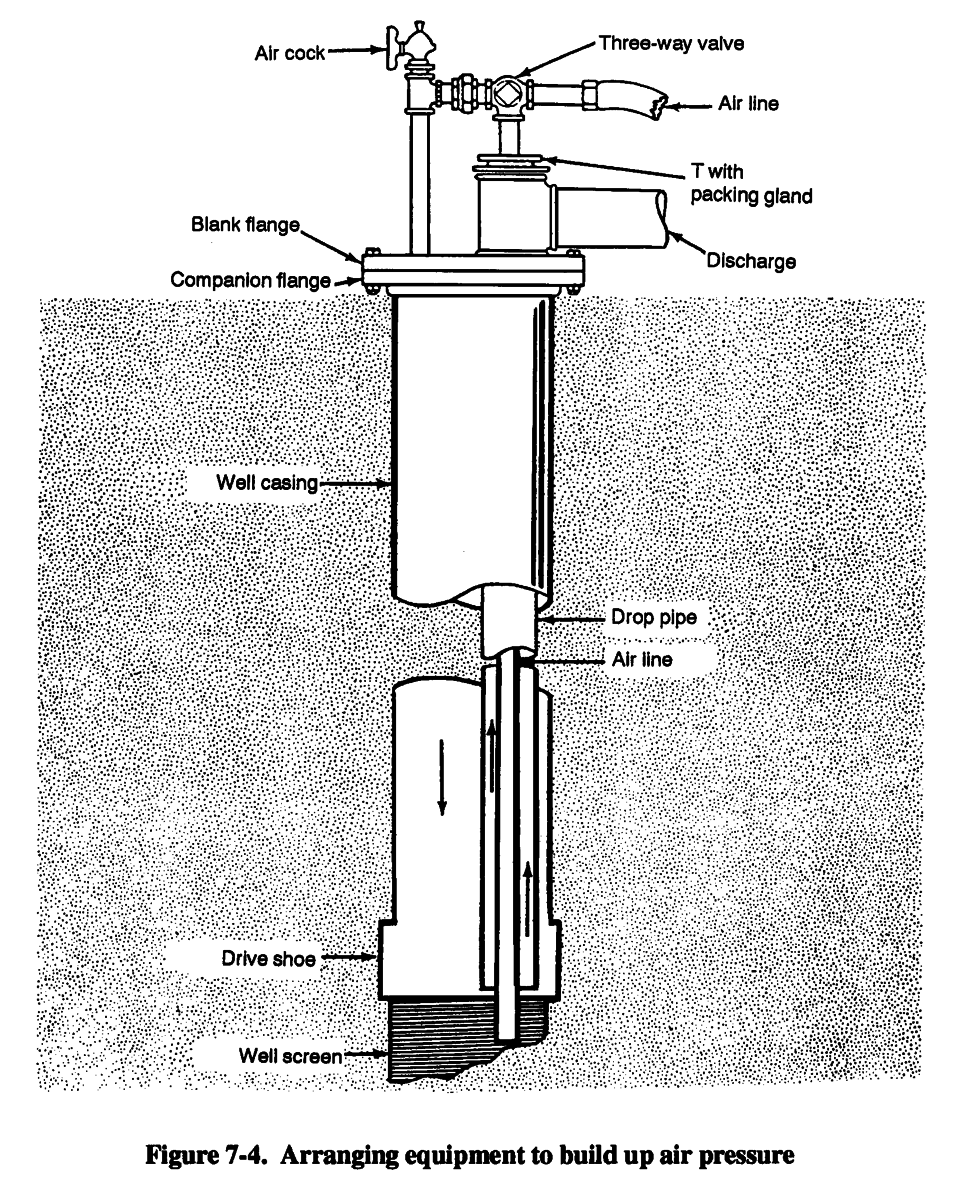
(2) Closed-Well Method. With this method, you use compressed air to close the top of the well with a cap and arrange the equipment so air pressure can build up inside the casing to force
water out through the screen openings (Figure 7-4, page 7-6).
7-5

FM 5-484/NAVFAC P-1065/AFMAN 32-1072
Disadvantages with this method are--
That valves and fittings may not be available for military field operations.
The danger of forcing water upward outside of the casing. This will loosen the casing and could ruin the well by bringing clay down into the formation.
7-6


FM 5-484/NAVFAC P-1065/AFMAN 32-1072
Use the following procedures to develop a well using this method:
Step 1. Arrange the equipment as in Figure 7-4, and turn the three-way valve to deliver
air down the air line, preferably with the air cock open. This will pump water out of the well through the discharge pipe.
Step 2. When clear water emerges, cut off the air and let the water in the well regain its static level.
Step 3. Listen to the air escaping through the air cock as the water rises in the casing to determine stability. Close the air cock and turn the three-way valve to direct the air supply down the bypass to the top of the well, forcing the water out of the casing and back through the screen. This technique will agitate the sand and break down any bridging of the sand grains. When the water has been pushed to the bottom of the drop pipe, air escapes through the drop line. You can prevent air logging of the formation by keeping the drop pipe above the well screen.
Step 4. Cut off the air supply and reopen the air cock so the water can reach the correct static level when you hear the air escaping from the discharge pipe or when the pressure stops increasing.
Step 5. Turn the three-way valve and direct the air supply down the airline to pump the well.
Step 6. Repeat this process until the well is thoroughly developed. You should not have to bail the well after developing it because the water velocity usually cleans out the sand from the well. However, if you did not initially bail the well thoroughly, you may have to repeat the bailing process to clean out the well.
7-2. Dispersion Treatment. Dispersing agents, mainly polyphosphates, when added to drilling fluid, backwashing, jetting water, or water standing in the well, counteract the tendency of mud to stick to sand grains. These agents are procured locally on an as-need basis. Baroid Industries produces Barafos, a white, granular, sodium tetraphosphate thinner and dispersant.
You may use chemicals such as sodium hexametaphosphate, tetra sodium pyrophosphate, sodium tripolyphosphate, and sodium septaphosphate to develop wells. Dispersants work effectively when applied at the rate of one-half pound of chemical to 100 gallons of water in the well. Let the mixture stand for about one hour before starting well development. Wetting agents, such as CON DET, increase the dispersion action of polyphosphates when added to the solution at a ratio of 1:100. Be careful when using the dispersion process because you could have an adverse reaction. The driller should make the decision to use or not to use dispersants.
7-3. Rock Development. Use this method to develop wells in rock formations. You can obtain good results by combining jetting with air-lift pumping from a limited zone isolated by inflatable packers. The objective is always to wash out fine cuttings, silt, and clay that have worked into the fissures, crevices, or pores of the rock during the drilling operations. Openings that remain plugged reduce water flow into the well. Develop the well thoroughly to remove all obstructing material.
When drilling through limestone formations, use acid to dissolve lime-like cementing material and to open up connections with joints or fissures beyond the borehole wall. However, such operations are rare in military well drilling.
7-7


FM 5-484/NAVFAC P-1065/AFMAN 32-1072
7-4. Well Protection and Treatment
a. External Preparations. You should disinfect and protect a well before starting the borehole.
Some other preventive measures are--
Stopping surface contaminants from entering the well.