nent washable type filters, follow carefully cleaning
accordance with applicable technical manuals and
directions supplied by filter manufacturer or consult
manufacturer*s instructions.
applicable technical manuals. Washable filters
b. Direct drive blower. Figure 6-29 shows a
should be renewed with adhesive spray following
typical arrangement of a blower with direct drive.
cleaning to enable them to pick up dust effectively.
(1) Blower speed adjustment. In alternating
c. Electronic air cleaners. This type unit
current applications, the blower speed is limited to
employs the principle of electrostatic precipitation.
the available motor speed. For example, a two
Particles in the air entering the unit become
speed motor will provide two blower speeds. In
positively charged and are attracted by the
direct current applications, motor controllers are
negatively charged collector plates and held there.
installed to provide a wide range of blower speed
Periodic washing of collector plates is required.
variation.
Application of adhesive coating on a prefilter may
(2) Other maintenance. Procedures for motor
be required. Follow carefully manufacturers*
and blower alignment and lubrication, and adjust-
instructions for proper maintenance of these units.
ment of blower bearings and thrust collars are the
d. Activated charcoal filters. These filters are in-
same as previously described for belt driven blow-
stalled in the return air plenum of warm air furnaces
ers.
or in self-contained purifying units consisting of one
or more activated charcoal filters, blower, and
housing. Disposable filters should be replaced
periodically per manufacturers* recommendations.
Manufacturer*s instructions should be followed for
the maintenance of permanent filters.
6-38.
Humidifiers.
a. Pan type humidifiers. Most humidifiers used
in Army warm air systems are the pan type with a
float to regulate the water level (figure 6-30). Be-
cause of the high temperature to which the float
valve is subjected, it frequently sticks in an open or
closed position. To release the valve, move the
float ball up and down to allow water pressure to
clean the dirt or other accumulation from the seat.
Frequent jiggling of this float control will prevent
sticking. If water is comparatively free of solids, the
humidifier float seldom requires service. If the
water condition is bad however, considerable diffi-
culty may arise. It is of prime importance to check
the installation of the pan to see that it does not
overflow on the combustion chamber or radiator of
the furnace. Pan type humidifiers must be regularly
cleaned to prevent accumulation of minerals
precipitating from the water. Chemicals specifically
made for use in humidifiers can be added to the pan
Figure 6-29. Direct drive blower.
to keep minerals in suspension until they can be
c. Heat exchangers and burners. Clean with a
flushed out. Biocides are also available which can
vacuum and/or brush.
be added to the pan to prevent algae and bac-
teriological growth. At the end of each heating
6-37.
Air filter maintenance.
season, turn off the water supply, clean the hu-
a. Replaceable type filters. Dirty filters impede
midifier and leave it empty until the next heating
air circulation, regardless of blower speed. If little
season.
or no air passes over the furnace, the building will
be insufficiently heated and the furnace will over-
6-29
TM 5-642
Figure 6-30. Pan type humidifier.
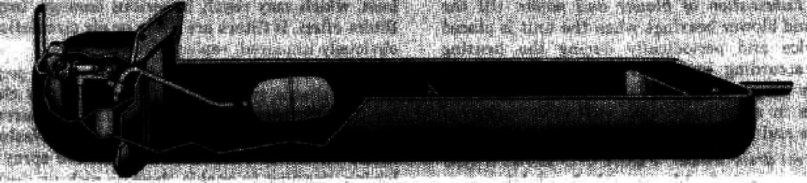
b. Other humidifiers. Other types of
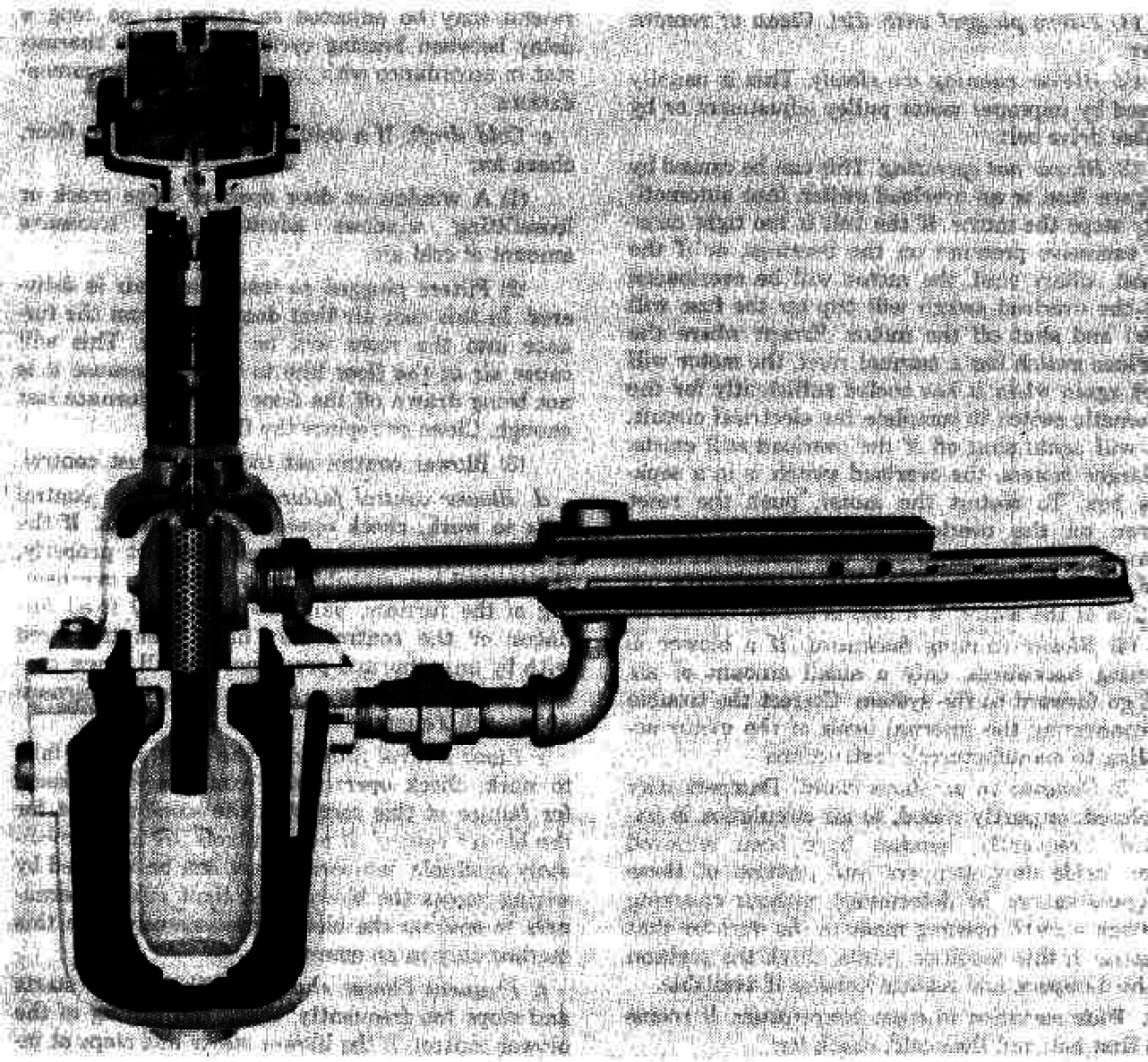
a separator, superheating it, and then distributing it
humidifiers used on Army installations are the
through a steam jacket manifold. Steam that has
centrifugal atomizer, steam spray, and steam
been treated with amine type chemicals should not
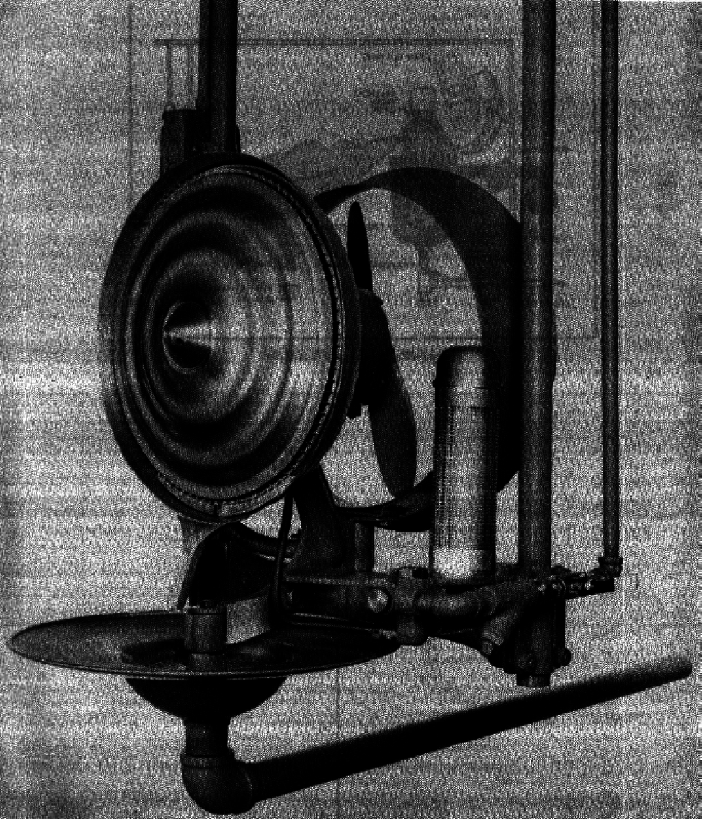
jacketed manifold types. With the centrifugal
be used for direct humidification. These chemicals
atomizer type (figure 6-31) a high speed rotating
are toxic and are carried over with steam. Steam is
disc imparts motion to a fine stream of water
normally free from minerals and thus mineral
directed against its center. Stationary blades further
accumulation on steam humidifiers is not a
atomize the water and direct it away from the disc
problem. It is good practice however, to clean this
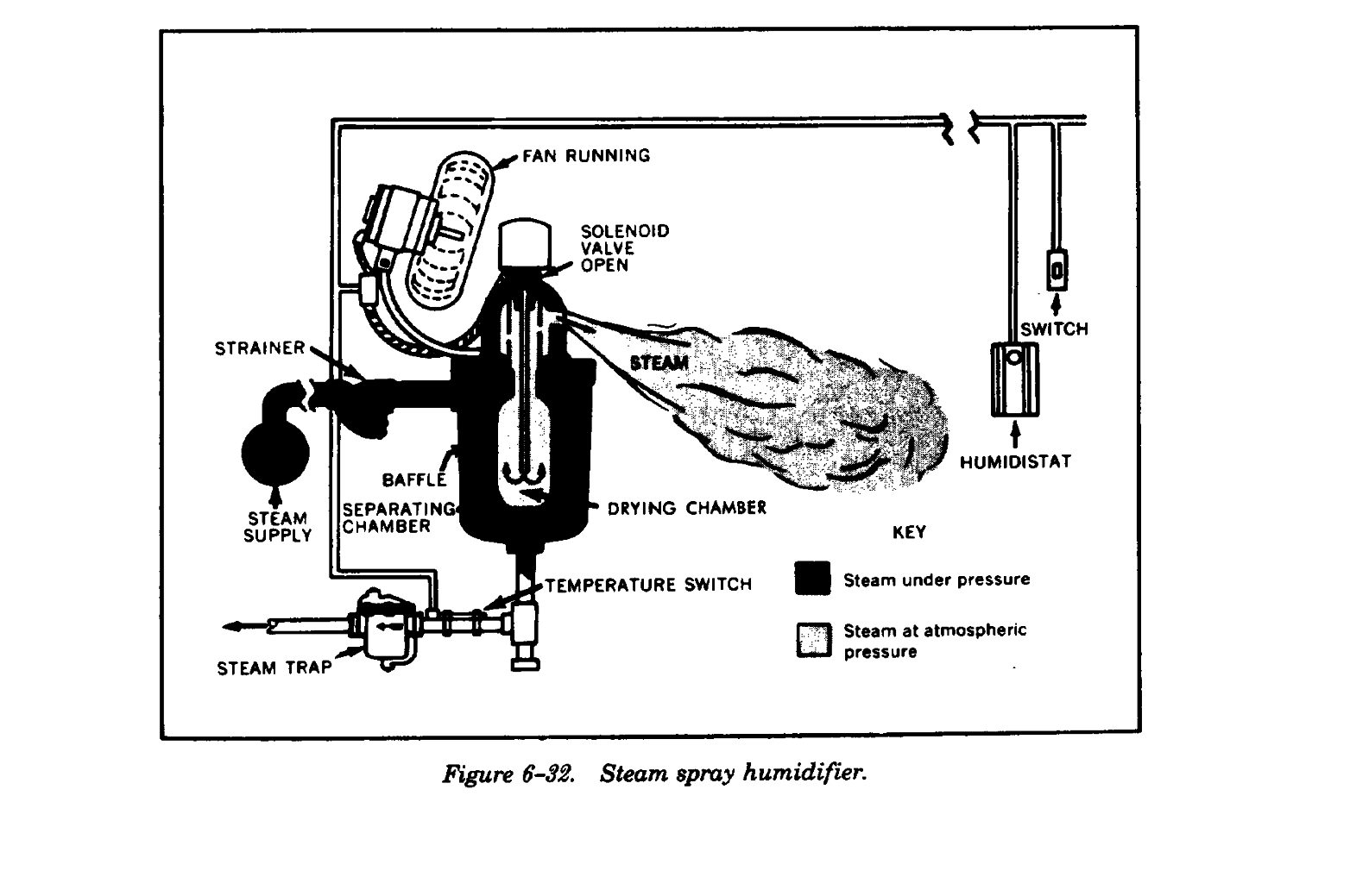
and housing. With the steam spray humidifier
type of humidifier each year to prevent nozzles
(figure 6-32) dry mineral free steam is produced
from clogging. Centrifugal humidifiers and
and discharged directly into the atmosphere. With
surrounding ductwork should also be cleaned
the steam jacketed manifold humidifier (figure 6-
annually.
33) steam is dried and purifled by passing it through
6-30
TM 5-642
Figure 6-31. Centrifugal atomizer humidifier.
6-31
TM 5-642
6-32
TM 5-642
Figure 6-33. Steam jacketed manifold humidifier.
6-39.
Blower and limit controls.
may be used in cold climates, or where a long duct
A combination blower and limit control is generally
is installed, or to meet some other local condition.
installed in the top of the furnace casing in an
b. Limit control adjustment. Set the limit control
opening provided by the manufacturer. It is in-
to turn off the fire at 175F in milder climates and
stalled 10 to 18 inches above the top of the com-
200F in colder climates, and to turn it back on at
bustion chamber and in a location that is easily
155F in milder climates and 170F in colder cli-
accessible for inspection and adjustment.
mates. Never set the limit control any higher than
a. Blower control adjustment. Set blower
necessary to keep the building at the proper tem-
control, or furnacestat, to stop blower between 90F
perature.
and 100F in the plenum chamber. Adjust the
control to start blower at 115F for gas or oil, and
6-40.
Troubleshooting.
125F for coal. The blower should run almost
Common operating difficulties and methods of cor-
continuously when the outside temperature is 40F
recting them are outlined below.
or below. The more continuously the blower runs,
a. Insufficient heat. If not enough heat is sup-
the better the building will be heated, particularly in
plied, check for:
cold weather. A slightly higher temperature setting
6-33
TM 5-642
(1) Filters plugged with dirt. Clean or remove
(2) Room thermostat out of adjustment. The
filter.
throttling range or anticipator setting on the ther-
(2) Blower running too slowly. This is usually
mostat may be adjusted so there is too long a delay
caused by improper motor pulley adjustment or by
between heating cycles. Adjust the thermostat in
a loose drive belt.
accordance with manufacturer*s recommendations.
(3) Blower not operating. This can be caused
c. Cold draft. If a cold draft is noticed on floor,
by a blown fuse or an overload switch that
check for:
automatically stops the motor. If the belt is too
(1) A window or door open or large crack or
tight causing excessive pressure on the bearings, or
loosefitting windows admitting an excessive
if the thrust collars bind, the motor will be
amount of cold air.
overloaded and the overload switch will trip (or the
(2) Filters plugged so insufficient air is deliv-
fuse will blow) and shut off the motor. Except
ered. In this case air that does come from the fur-
where the overload switch has a manual reset, the
nace into the room will be very hot. This will cause
motor will start again when it has cooled
air at the floor line to be cold because it is not being
sufficiently for the automatic switch to complete
drawn off the floor into the furnace fast enough.
the electrical circuit, but will again shut off if the
Clean or replace the filters.
overload still exists. In larger motors, the overload
(3) Blower control set too low; adjust control.
switch is in a separate box. To restart the motor,
d. Blower control failure. If the blower control
push the reset button on the overload switch.
fails to work, check operation of contacts. If the
Whenever the motor is found to be cutting out
control fails to make or break contact properly, the
because of overload, eliminate the overload before
control has probably been ruined by overheating of
continuing operation of the motor. If a fuse is
the furnace, particularly in coal fired furnaces; or
blown, replace it.
the control may have been tampered with by
(4) Blower running backward. If a blower is
unauthorized personnel. Install a new control. Do
running backwards, only a small amount of air will
not operate a forced warm air furnace without this
go forward to the system. Correct the trouble by
control.
connecting the internal leads of the motor ac-
e. Limit control failure. If the limit control fails
cording to manufacturer*s instructions.
to work, check operation of contacts. The reason
(5) Dampers in air ducts closed. Dampers may
for failure of this control is the same as that for the
be closed, or partly closed, so air circulation is im-
blower control. If new controls are not immediately
peded. Frequently, handles have been removed
available, temporary heat can be obtained by wiring
from inside duct dampers and position of these
across the blower and limit control terminals to
dampers cannot be determined without checking
operate the blower continuously. Use this method
through a small opening made in the duct for that
only in an emergency.
purpose. If this condition exists, check the position
f.
Frequent blower shutoff If the blower starts
of the dampers, and replace handles if available.
and stops too frequently, check the setting of the
b. Wide variation in room temperature. If rooms
blower control. If the blower starts and stops at in-
are first hot, and then cold, check for:
tervals of 2 or 3 minutes, motor life will be short-
(1) Blower control set too high. If the blower
ened. This also overheats the overload switch in the
control setting is too high, the blower will not start
blower control. Increase the differential between
until the furnace is very hot and a surplus of heat is
starting and stopping temperatures on blower
then blown into the building. Set blower control
control by 10F. This will usually overcome the
down in accordance with recommendations for
difficulty.
blower control settings. To test for this condition,
g. High outlet temperature. Outlet temperature
turn on the manual switch controlling the blower
should not exceed 160F for an extended period of
and permit it to operate continuously. If this
time. The most frequent cause of high outlet tem-
relieves the condition, the blower control is set too
perature is insufficient airflow. This can be caused
high.
by blocked filters, too low a fan speed, or restricted
ductwork.
6-34
TM 5-642
Section VIII. ENERGY CONSERVATION
6-41.
Space temperature setback.
6-42.
Maintenance of duct insulation.
Energy expended to heat buildings to comfort con-
a. Warm air ducts are commonly installed with-
ditions when they are unoccupied is wasted. Save
out insulation and are typically routed from the
energy by setting back the temperature level at
equipment room through unoccupied spaces, shafts,
these times. The savings which can result vary with
and ceiling voids where their heat loss is
the length of time and the number of degrees that
unproductive in meeting the occupied space heating
temperatures are set back. The percentage savings
load. Although the temperature difference between
will be greater in warmer climates, but the gross
duct and ambient temperature is relatively small,
energy saved will be greater in cold climates. In
heat loss in long duct runs can be significant.
areas where it is not necessary to maintain high
b. Of equal importance is the temperature drop
temperatures during occupied periods, i.e. corridors
of supply air that accompanies heat loss. In long
and lobbies, maintain even lower temperatures than
duct runs serving many rooms on one zone, this
for the other spaces. Implement setback by
will result in the last room having a lower supply air
resetting thermostats manually (if automatic
temperature than the first. The tendency in this case
setback control has not been installed), or adjusting
is to heat the last room to comfort conditions
controls to suggested temperatures (if clock, day-
resulting in overheating in each preceding room.
nite, or other automatic reset controls are
c. Warm air ducts may be insulated with rigid
available). Climate, type of system, and building
fibrous material stuck on or fixed with special clips
construction will determine the length of the startup
or bands. They may also be insulated with flexible
period required to attain daytime temperature
mats clipped or wired on (this is particularly
levels. Experiment to decide upon the optimal
applicable for round or oval ducts). Ducts may also
setback temperature and startup time for any
be insulated with spray-on foam or fibrous material
particular building. If, in extremely cold weather,
as used for insulating undersides of roofs. It is
experience indicates that the heating system does
worth considering insulating roofs and ducts as one
not raise the temperature sufficiently by the time the
contract.
building opens for the day, set temperatures back to
d. Insulation applied to ducts supplying only
a level higher than those recommended here for
warm air need not be vapor sealed. Insulation ap-
those periods of time only. So called “smart
plied to ducts supplying warm air in winter and cold
thermostats” and computerized Energy Monitoring
air in summer must be vapor sealed to prevent
and Control Systems (EMCS) automatically
condensation forming within the insulation.
calculate the most effective time to end setback.
6-35
TM 5-642
APPENDIX A
RELATED PUBLICATIONS
Government Publications.
Department of the Army.
TM 5-650
Central Boiler Plants
TM 5-745
Heating, Ventilating, Air Conditioning and Sheet Metal Works
TM 5-785
Engineering Weather Data
TM 5-810-1
Mechanical Design-Heating, Ventilating and Air Conditioning
TM 5-843-3
Ground Storage of Coal
Non-Government Publications.
Air Conditioning and Refrigeration Institute (ARI), 1501 Wilson Blvd., 6th Floor., Arlington, VA
22209
Guideline F-88
Selection, Installation and Servicing of Residential Humidifiers
Standards:
610-82
Central System Humidifiers
670-85
Fans and Blowers
680-86
Residential Air Filter Equipment
American Boiler Manufacturers Association (ABMA), Suite 160, 950 N. Glebe Rd., Arlington, VA
22203
Boiler Water Limits and Steam Purity Recommendations for Watertube Boilers (3rd Edition, 1982)
Boiler Water Requirements and Associated Steam Purity for Commercial Boilers (1st Edition, 1984)
Guidelines for Burner Adjustments of Commercial Oil-Fired Boilers
A Guide to Clean and Efficient Operation of Coal Stoker Fired Boilers
Lexicon — Boiler and Auxiliary Equipment (5th Edition, 1987) Operation and Maintenance Safety
Manual
Thermal Shock Damage to Hot Water Boilers as a Result of Energy Conservation Measures
American Gas Association (A GA), 1515 Wilson Blvd., Arlington, VA 22209
Directory of Certified Appliances and Accessories
Standards:
Z21.8-84
Installation of Domestic Gas Conversion Burners
Z21.13-87
Gas-Fired Low Pressure Steam and Hot Water Boilers
Z21.47-87
Gas-Fired Central Furnaces
Z21.66
Automatic Vent Damper Devices for Use with Gas-Fired Appliances
Z83.6-87
Gas-Fired Infrared Heaters
Z83.8-85
Gas Unit Heaters
American Society of Heating, Refrigeration, and Air Conditioning Engineers (ASHRAE), 1791
Tullie Circle, NE., Atlanta, GA 30229
Handbooks:
HVAC Systems and Applications, 1987
Equipment, 1988
Fundamentals, 1989
A-1
TM 5-642
American Society of Mechanical Engineers (ASME), 45 East 47th Street, New York, NY 10017
Boiler and Pressure Vessel Code, and Interpretations:
Section IV
Construction of Heating Boilers
Section VI
Recommended Rules for Care and Operation of Heating Boilers
Section VIII
Pressure Vessels, Division 1
National Fire Protection Association (NFPA), Batterymarch Park, Quincy, MA 02269 National Fire
Codes:
31
Standard for Installation of Oil Burning Equipment
54
National Fuel Gas Code
85A
Standard for Prevention of Furnace Explosions in Fuel-Oil and Natural
Gas-Fired Single Burner Boiler Furnaces
851
Recommended Practices for Stoker Operation
Sheet Metal and Air Conditioning Contractors* National Association (SMACNA), 8224 Old
Courthouse Rd., Vienna, VA 22180
HVAC Duct Construction Standards, Metal and Flexible
HVAC Systems — Testing, Adjusting and Balancing
Installation Standards for Heating, Air Conditioning and Solar Systems
A-2
TM 5-642
APPENDIX B
TROUBLESHOOTING UNDERFEED STOKERS
Symptom
Probable cause
Remedy
Using too much fuel.
Thin fuel bed due to excess air Decrease air supply or increase coal
from fan.
feed.
Thin fuel bed due to too much Adjust overfire draft by resetting
draft.
dampers, or installing automatic
dampers.
Dirty heating surface.
Keep heating surfaces clean of soot
and fly ash.
Insufficient heat.
Not enough coal feed (thin fuel Increase rate of feed and adjust air
bed).
from fan.
Fuel bed too deep.
Increase air supply, decrease fuel
feed.
Improper furnace draft.
See that overfire draft is sufficient to
carry away products of com-
bustion. Check design and con-
dition of chimney.
Limit control set too low.
Adjust limit control to weather
conditions. Increase settings
during cold weather, decrease
during warm weather.
Excessive heat.
Fuel bed too heavy.
Decrease coal feed, adjust air
supply.
Limit control set too high.
Lower setting.
Hold-fire or out-fire control set Hold-fire controls are made to keep
improperly,
fire from going out.
Set to hold fire only; set 2 minutes
for each ½ hour.
Excess furnace draft. (Fire goes Adjust draft controls to lower draft.
out during off period)
Insufficient draft.
Chimney may be blocked or too
small. Reset draft controls to in
crease draft.
Insufficient air in furnace room.
Increase combustion air openings in
furnace room.
Dirty fuel bed.
Remove excess fly ash and clinkers
from fire.
Coke trees.
Adjust air supply to fuel feed,
check furnace draft.
Overload or pin sheared.
Clinker in retort.
Maintain clean fires and proper
adjustment of stoker.
B-1
TM 5-642
Symptom
Probable cause
Remedy
Obstruction in feed tube.
Shut off stoker and remove ob-
struction.
Feed screw worn or broken.
Replace feed screw.
Coke ball in retort.
Remove coke ball, adjust feed and air
supply.
Smoke from chimney.
Insufficient combustion air.
Increase air. Check tuyere openings,
windbox, fan blade and heating
surfaces; clean if necessary.
Insufficient combustion space.
Consult stoker manufacturer.
Smoke from fire door.
Insufficient furnace draft or too Increase draf

Reads:
192
Pages:
58
Published:
Feb 2024
Unlock the treasure trove of knowledge with '500 Trivia Questions and Answers for Smart Kids'! This captivating book is designed to ignite the curiosity of yo...
Formats: PDF, Epub, Kindle, TXT

Reads:
633
Pages:
61
Published:
Feb 2024
"Try Not to Laugh! 1000 Hilarious Jokes for All Ages." is packed with rib-tickling humor and endless entertainment, this uproarious collection is guaranteed t...
Formats: PDF, Epub, Kindle, TXT

Reads:
27
Pages:
139
Published:
Mar 2023
This 11th volume “A Tribute To….” of the Sci-Fi Film Fiesta series is dedicated to the actors, directors, producers, special effects artists, writers and othe...
Formats: PDF, Epub, Kindle

Reads:
11
Pages:
48
Published:
Feb 2023
The SCI-FI FILM FIESTA eBook series is intended as a salute to the pioneering work of science fiction film makers. May future generations have the privilege o...
Formats: PDF, Epub, Kindle, TXT