Section I. DESCRIPTION OF SYSTEMS
6-1. Warm air furnaces.
connection is made below all parts of the furnace
The primary function of a warm air furnace is to
which radiate enough heat to cause a countercur-
burn fuel efficiently and to transfer the heat gen-
rent of warm air, because such a current opposes
erated to the circulating air of a warm air heating
the flow of cooled air into the furnace.
system. Most furnaces consist of a combustion
(2) The most common source of trouble in
chamber (primary heating surface). The furnace
gravity systems is insufficient duct area, usually in
may be cast iron, steel, or a combination of the two.
the cold air (return) duct. The total cross-sectional
The heat transfer per unit area of heating surface is
area of the cold air duct(s) must be at least equal to
essentially the same for cast iron and steel where
the total cross-sectional area of all warm air
both are operated at the same temperature
(supply) ducts. If it is necessary to supply additional
difference. With either cast iron or steel, thicker
heat to a space at the end of a long duct run, this
material yields longer life without materially
can be accomplished by throttling the balancing
affecting heat transfer. The furnace may be fired
dampers in other supply ducts to favor the deficient
with any of the common fuels and may be of the
area or installing a booster fan in the deficient duct
gravity or forced air type. Gravity warm air
to force the air stream.
furnaces depend upon convection currents to obtain
the head required to produce the airflow; forced air
furnaces produce the necessary airflow with fans or
blowers and are usually equipped with air filters.
6-2. Gravity warm air heating systems.
Operation of gravity warm air heating systems is
dependent upon the difference in density (weight)
of warm and cold air. Warm air is less dense
(lighter) than cooler air and will rise if cooler air is
available to displace it. Satisfactory operation of a
gravity warm air heating system depends upon
three interrelated factors: size and “pull” of the air
ducts; building heat loss and; the heat available
from the furnace.
a. Ducted gravity systems.
(1) In a ducted gravity system (figure 6-1),
warm air is conveyed from the furnace bonnet (top
section of the furnace casing), through metal ducts,
to the spaces to be heated. Vertical ducts (stacks)
connect with registers usually installed in room
baseboards, floors, or sidewalls just above the
baseboards. Stacks are generally located within
inside partitions to prevent chilling of the supply air
b. Ductless gravity systems. Ductless gravity
and consequent reduction in head; cooled air return
furnaces are often installed on floor level; they are
registers may be located in either cold or warm
simply oversized jacketed space heaters. The most
walls, but cold walls are preferred (unless a long,
common difficulty experienced with this type of
high-friction-loss duct is required). Gravity warm
furnace is a return air opening (at the floor) of in-
air systems often have only one or two centrally
sufficient area. The return air opening should be
located return registers, all on the first floor.
made on two or three sides wherever possible. In-
Upstream of the furnace casing, return ducts
sulation should be provided above the furnace to
usually join a single large duct which enters the
avoid possible fire hazards.
casing near the floor or furnace foundation. This
6-1
TM 5-642
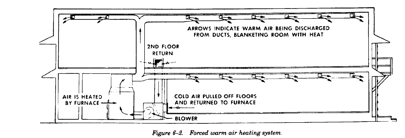
6-3. Forced warm air heating systems.
allowing the most convenient duct runs to be
The principal of operation of forced air heating
installed. Figure 6-2 shows a typical forced air
systems differs from that of gravity heating systems
heating system. In addition to the prime movers
in that a fan or blower is included in the former to
(fans), the components of a forced air heating
insure and regulate air movement. Due to the
distribution system include supply and return ducts,
assistance of the fan, duct pitch can be disregarded
registers, dampers, and insulation.
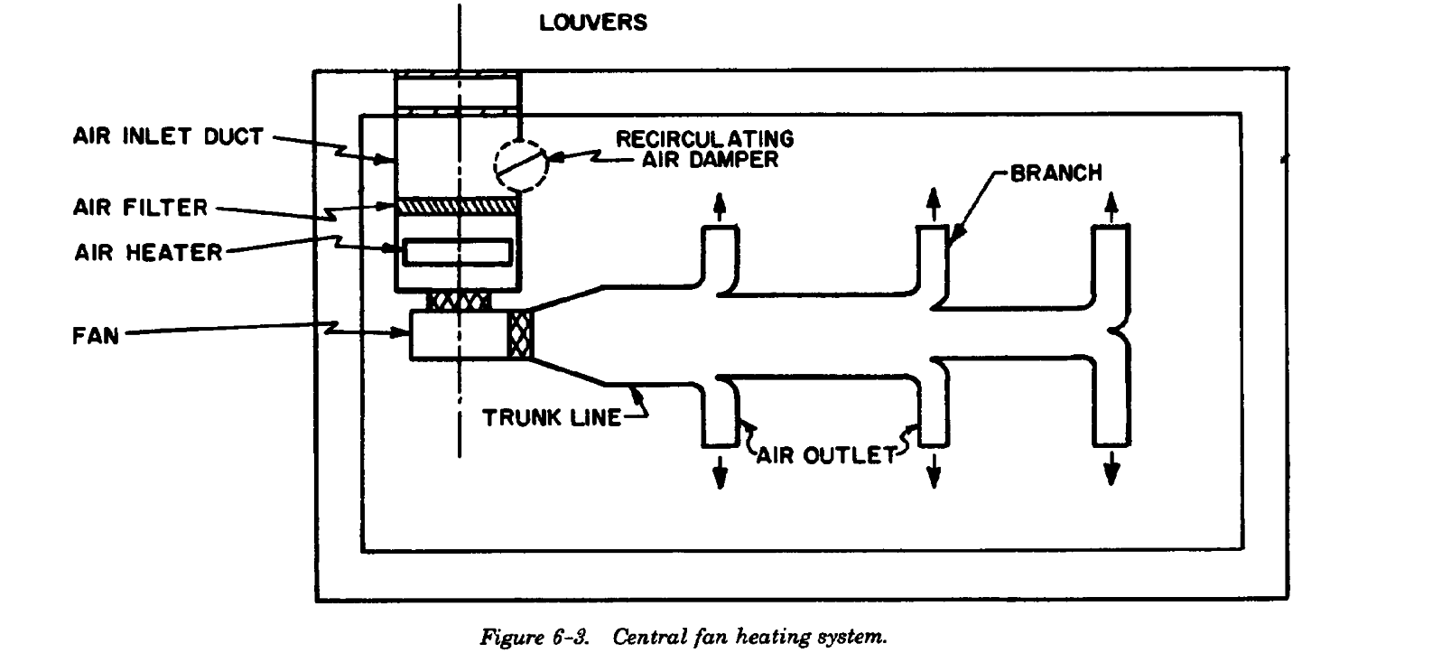
a. Outside wall delivery system. In this system,
the heated area. The damper may be modulated or
supply grilles are located along the outside (perim-
fixed in position.
eter) walls, near the sources of greatest heat loss.
(2) Air filter. An air filter is located in the inlet
These supply grilles (or registers) are designed to
air duct, just upstream of the air heater.
blanket the perimeter areas and mix with the cold
(3) Return air damper. A return air damper,
air from infiltration points thereby reducing or
installed upstream of the air filter, permits a regu-
eliminating discomfort due to drafts.
lated recirculation of heated air into the outside air
b. Central fan delivery system. This system
inlet duct. The combined operation of this damper
(figure 6-3) sometimes performs both heating and
and the outside air damper (which controls the
ventilation functions in large buildings. The air
influx of cold air) provides for tempering the
heaters in this system are heat exchangers consist-
outside air introduced into the system.
ing of pipe coils, finned tubes, or cast iron sections
(4) Air heater. The air heater (a heat exchanger
connected into stacks or units by nipples. The in-
heated by steam or hot water) is located in the
termediate heat carrier is either hot water or steam
mixed air duct, downstream of the air filter.
(from boilers, convertors, etc.) circuited through
(5) Fan. A motor operated fan, located after
the heating elements of the heat exchanger. A fan
the air heater, draws the tempered air through the
blows (or draws) air through the air heater and
heat and discharges it to a trunk line. “Blow-
supplies it to the spaces to be heated through the
through” arrangements locate the fan upstream of
distribution ductwork. Because the amount of air
the air heater.
required for heating purposes usually exceeds that
(6) Trunk line. This is a main duct with indi-
required for ventilation, economy of operation is
vidual branches taken off at intervals to carry the
improved by recirculating a portion of the heated
tempered air to the required spaces. Dampers at
air. A common central fan delivery system includes
either the branch take-off points or the branch
the following:
outlets provide balanced air distribution. The duct
(1) Outside air inlet duct. This duct is fitted
may be made from galvanized steel sheets; both
with a damper to control the influx of outside air to
aluminum and non-metallic ducts also are used extensively.
6-2
TM 5-642
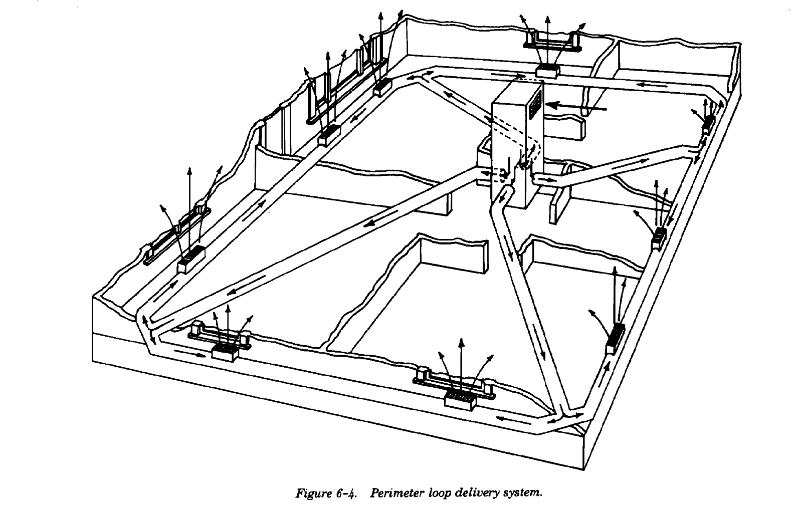
c. Perimeter delivery systems. Perimeter systems
furnace is located. In perimeter systems, a
usually employ the outside wall delivery system. Air
downflow furnace is normally used. In this type
returns to the furnace through centrally located,
furnace, cold air enters the unit from above and is
high sidewall or ceiling grilles. Return ducts may be
discharged as warm air from the bottom or lower
located in attics or other unheated spaces. Return
part of the furnace casing. Figure 6-4 illustrates one
air may be taken from crawl spaces and basements,
type of perimeter system called a loop system.
but never from a confined space in which the
6-3
TM 5-642
d. Inside wall delivery system. Supply grilles are
sired spaces. With annular ceiling diffusers, the
located on an inside (warm) wall, either high or
airstream is spread a full 360 degrees and the rate
near the floor. Return registers are located near the
of diffusion is high; however, the throw is rather
greatest exterior exposure. High wall registers
short, requiring (or in some cases allowing) high air
deliver the air either horizontally or slightly down-
discharge velocities.
ward, so that it does not strike the ceiling or wall.
For best results, multi-directional grilles are used,
6-4. Ratings of warm air furnaces.
distributing the airflow uniformly. To reduce the
Furnace rating is usually determined by BTU de-
discharge velocity, grilles are used with an area
livery per hour at the bonnet. Standard ratings for
larger than that of the connecting duct. Location of
different manufacturer*s furnaces can be obtained
the warm air return grille depends on the location
from the various trade associations, depending
of the supply grilles.
upon the type of fuel fired by the furnace.
e. Ceiling delivery system. This system employs
ceiling diffusers to deliver the warm air to the de-
Section II. COAL FIRED WARM AIR FURNACES
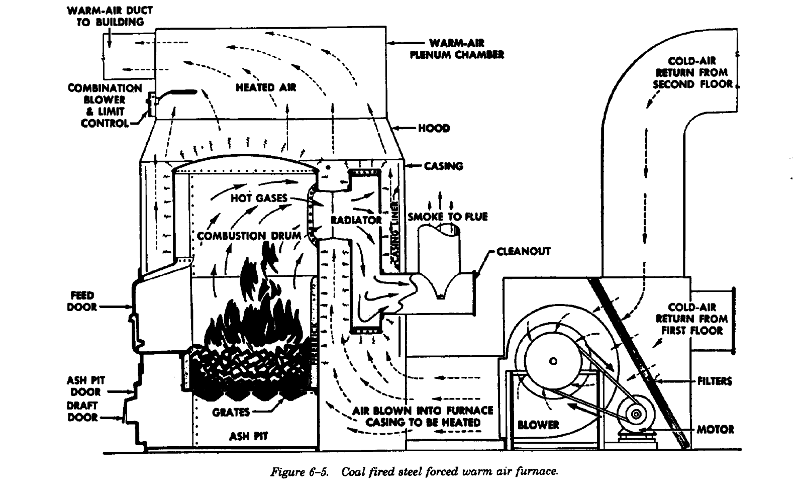
6-5. Steel furnaces.
(secondary heating surface) attached to the rear of
Steel furnaces (figure 6-5) are constructed of heavy
the combustion chamber. In large sizes, two addi-
gauge steel, riveted and caulked or welded at the
tional radiators may be installed on the sides of the
joints to make them air-tight. The fire-feed, ashpit,
furnace. All radiators must have a cleanout
and draft doors, usually made of cast iron, are
opening. Steel furnaces are, in general, more
located at the front of the furnace. In smaller sizes,
common than cast iron furnaces on Army installations.
steel furnaces usually have a single radiator
6-4
TM 5-642
6-6. Cast iron furnaces.
x [BTU content per pound of coal] x [0.65
Cast iron furnaces are constructed in sections which
(efficiency)]
are made airtight by the use of liberal amounts of
b. Furnaces with more than 294,000 BTUH
furnace cement. Use cement supplied by the furnace
output.
manufacturer in a fashion consistent with the
BTUH output at the furnace bonnet = [area
manufacturer*s recommendations. The radiator
of grate in square feet] x [10.0 pounds of
(secondary heating surface) is usually located on
coal] x [BTU content per pound of coal] x
top of the combustion chamber dome. Both steel
[0.70 (efficiency)]
and cast iron coal fired furnaces must be installed
on a solid masonry base. Do not install on a base
6-8. Smokepipe.
made with wood or other combustible material.
The smokestack from furnace to chimney must be
18 gauge or heavier steel, and at least as large (in
6-7. Ratings and sizes.
cross-sectional area) as the furnace collar. Avoid
Ratings are determined by BTU per hour (BTUH)
the use of elbows wherever possible. Install the
delivery at the bonnet. Standard code ratings are
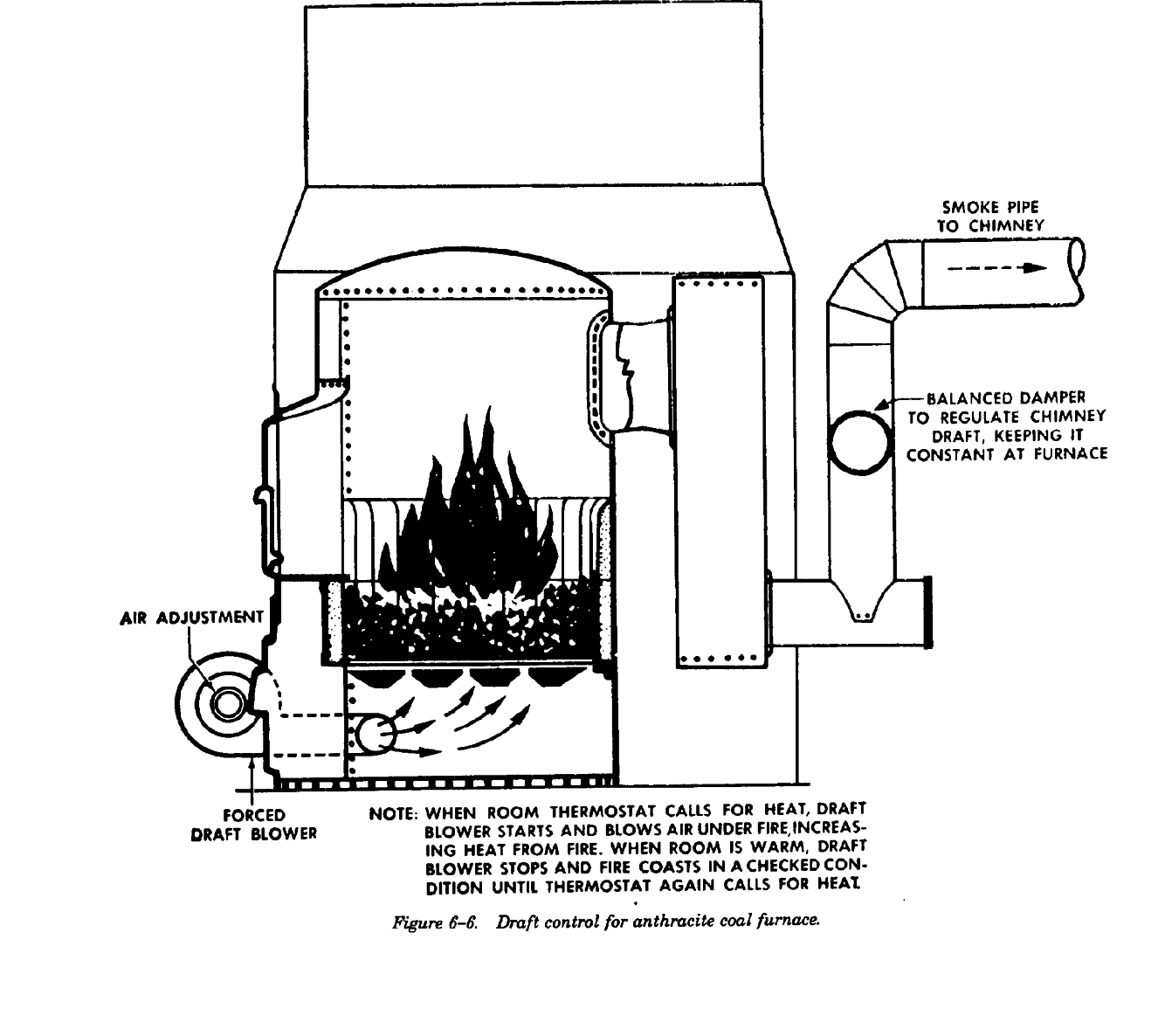
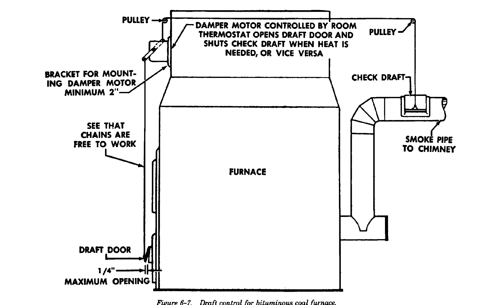
check draft used with bituminous or anthracite coal
used in sizing coal fired furnaces, in accordance
with hinges on the top sides of the smokepipe for
with the following formulas:
easy (chain) operation by the damper motor. For
a. Furnaces with 294,000 BTUH or less output.
buckwheat coal, a checkdraft is generally omitted,
BTUH output at the furnace bonnet = [area
but a balanced atmospheric type damper should be
of grate in square feet] x [7.5 pounds of coal]
installed to regulate chimney draft. (See figures 6-6
and 6-7.)
6-5
TM 5-642
6-6
TM 5-642
6-9. Motor damper.
used, particular attention must be given to them.
Install the motor damper such that it has no direct
Rectangular chimneys must be carefully checked,
contact with the furnace or bonnet. Motors
from the standpoint of both area and dimensions.
installed on the bonnet or furnace are should be
a. Area. A chimney must have a cross-sectional
mounted on a bracket which extends out to allow
area greater than or equal to that of the smoke-pipe
for air passage, or are mounted on insulators to
outlet from the furnace. The smaller dimension of
prevent excessive heating.
of a rectangular flue must be at least two-thirds of
the smokepipe diameter. Chimney cross-sectional
6-10.
Chimney.
area must be increased 4 percent for each 1,000
feet of elevation above sea level.
The importance of the chimney in the proper com-
b. Height. Follow manufacturer*s recommenda-
bustion of coal cannot be overemphasized. Every
tions on chimney height at all times. Height of the
pound of coal requires from 150 to 250 cubic feet
chimney may be 85 percent of the recommended
of air for proper combustion; sufficient draft must
height without requiring compensation; however,
be maintained through the fuel bed to supply this
for each 10-percent decrease below recommended
amount of air. A blocked chimney or chimney
height, add 6 percent to the grate area to get the
downdraft can cause inadequate draft and there-
same furnace heat output (BTUH). All chimneys
fore, incomplete combustion and create carbon
must extend at least 2 feet above the peak of the
monoxide. A chimney must have sufficient area and
roof and in no cases should chimney height be less
height, and must be tight from bottom to top. The
than 15 feet, even for small furnaces.
most efficient chimney shape is round; however,
because rectangular chimneys are commonly
6-7
TM 5-642
Section III. OIL FIRED WARM AIR FURNACES
6-11.
General description.
6-13 Oil conversion furnace.
Oil fired furnaces may be designed and built exclu-
Coal furnaces may be modified for oil firing capa-
sively for use with fuel oil, or oil conversion burn-
bilities by installing oil conversion burners in ex-
ers may be installed in furnaces originally burning
isting coal furnaces.
coal. Standard design and installation practices for
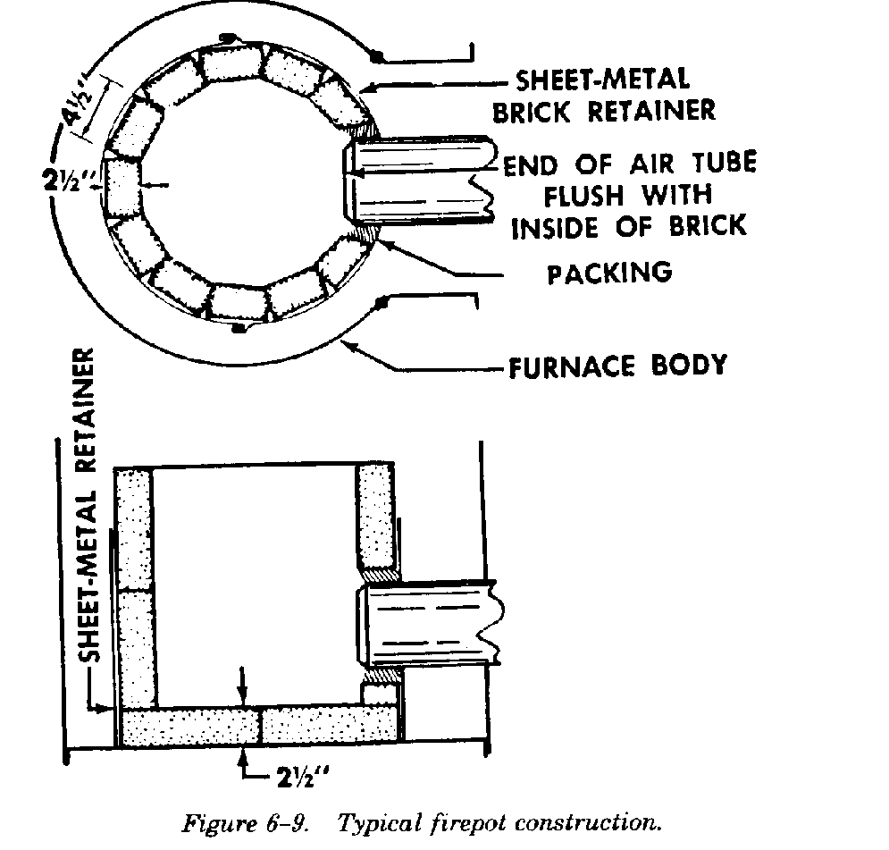
a. Firepot. The firepot may be either round or
fire prevention are detailed in the applicable codes,
square. Normally, a 24-gauge sheet metal drum is
technical manuals, and manufacturer*s literature.
set on a brick floor inside the furnace. The sheet
metal acts as a retainer for the firepot wall. Bricks
6-12.
Oil furnaces.
are cemented with special mortar, made for the
With oil furnaces, maximum efficiency (beyond that
particular brick used. The space between the fire-
possible with oil conversion burners) is the result of
pot wall and the furnace body is not filled. Heat is
proper sizing of the combustion chamber and the
allowed to flow behind the refractory pot. In gravi-
firepot volumes, longer heat travel, and very large
ty warm air installations, a radiation shield is in-
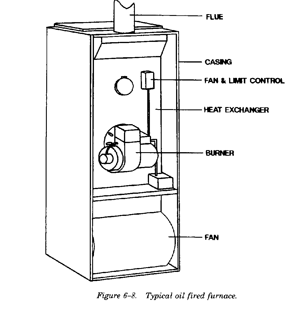
heating surfaces. Oil furnaces are usually of the
stalled between furnace body and casing to prevent
blowthru type, with an air space pressure greater
radiant heat from retarding cold air circulation.
than the combustion chamber pressure. Compact
Refer to figure 6-9 for typical firepot construction.
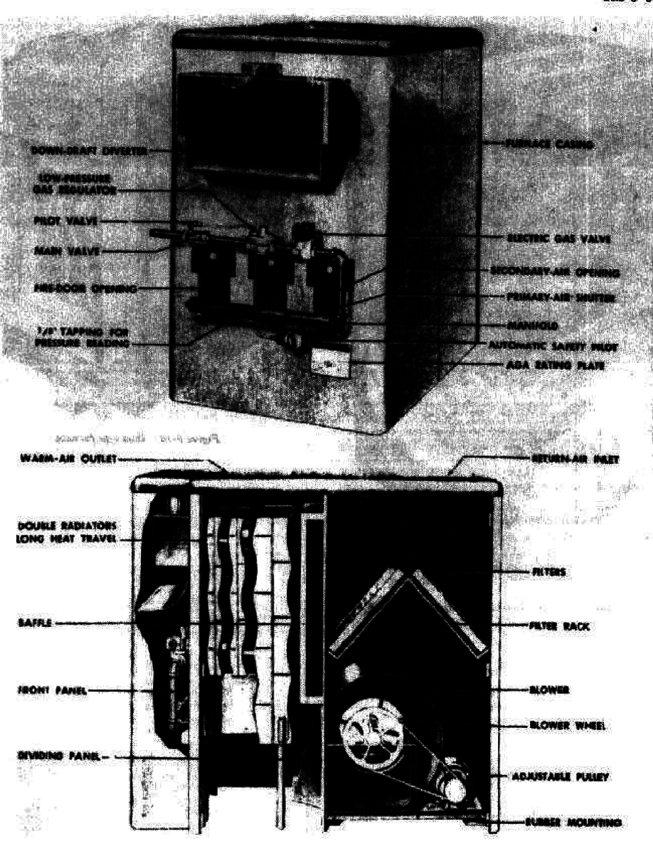
fan-furnace-burner units may be installed in
basements, attics, or other locations with limited
space. Figure 6-8 illustrates a typical oil fired
furnace.
b. Oil conversion burner installation.
(1) Installing burner.
(a) Set burner with end of blast tube flush
with the inside wall of the firepot. (See Table 6-1
and firepot diagrams, figures 6-10 and 6-11.)
6-8
TM 5-642
6-9
TM 5-642
(b) Pack around the blast tube to close the
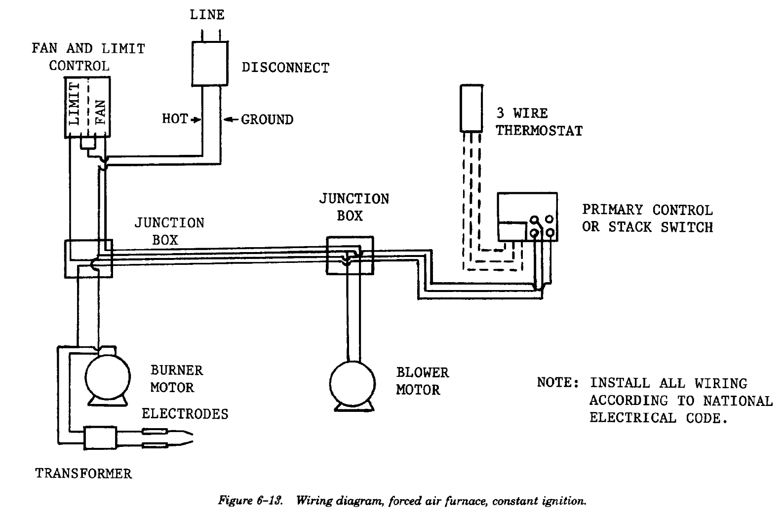
(2) Installing constant ignition controls.
gap between the refractory and the burner blast
(a) Select the appropriate wiring diagram
tube. This prevents the flame from licking back on
from figures 6-12 and 6-13, depending on the air
the blast tube and eventually burning it off. Leave
distribution system type (gravity or forced air).
a groove at the bottom of the packing so that oil
These diagrams are for constant ignition burners.
dripping from the blast tube can drain into the
firepot.
(c) Secure the burner to the floor with lag
screws unless some other provision has been made
in the furnace unit for locking the burner in place.
6-10
TM 5-642
6-11
TM 5-642
(b) Check the polarity of the wiring circuit
quent burner cycling and temperature fluctuations
carefully to ensure that “hot” and ground connec-
within the building. In no case should the nozzle
tions are as shown in the appropriate wiring dia-
ever be sized larger than the input rating of the
gram.
furnace. Assuming a furnace efficiency of 70 per-
(c) Note that the burner motor and ignition
cent, the nozzle can be sized as follows:
transformer are wired in parallel; that is, one wire
Nozzle Rate, GPH=(BTUH Heat Loss)/(138,200
from each is connected to the “hot” line and the
x .70)
remaining wire from each is connected to the
(4) Nozzle selection. Choose nozzles used in
ground wire. If RF suppression (radio filter) is re-
small units carefully. If a new unit using a new
quired, it should be wired in parallel with both the
nozzle does not produce a perfect fire, try several
burner motor and ignition transformer.
other nozzles with the same markings. Trouble can
(3) Nozzle sizing. Size the nozzle so that the
occur even with new nozzles despite care used in
furnace will provide enough heat to match the cal-
its selection. For this reason, keep several spare
culated heat loss of the building at design condi-
nozzles in stock.
tions. Oversizing results in lowered efficiency, fre-
Section IV. GAS FIRED WARM AIR FURNACES
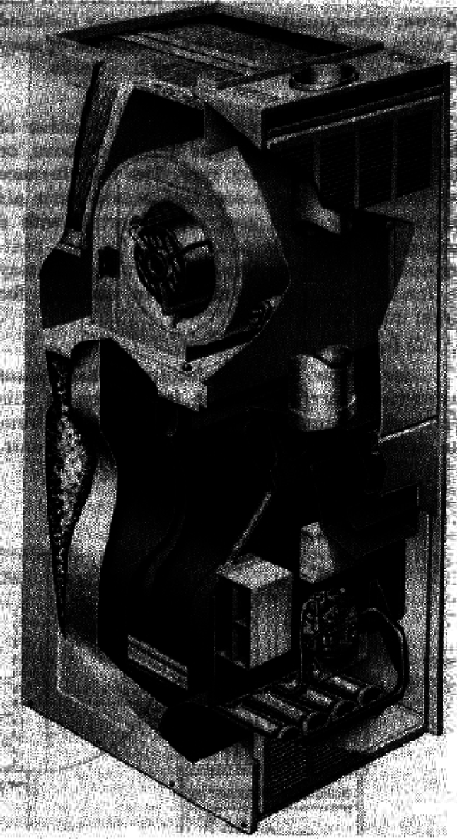
6-14.
General.
or “Hi-Boy” type with the combustion chamber
Gas fired warm air furnaces may be of the central
above the blower (figure 6-15), or they may be of
type with the blower mounted on the same level as
the duct or horizontal radiator type (figure 6-16).
the combustion chamber (figure 6-14), the elevated
6-12
TM 5-642
Figure 6-14. Gas fired central furnace.
6-13
TM 5-642
Figure 6-16. Duct type furnace.
Figure 6-15. Gas fired elevated upflow furnace.
6-14
TM 5-642
6-15.
Construction.
Air is directed through the blower and heat ex-
Gas fired warm air furnaces are made of cast iron
changer and is discharged at the bottom of the unit.
or steel. They are usually constructed with one or
These type units are typically used in underfloor air
more radiators or special radiating surfaces to
distribution systems. Figure 6-17 shows a typical
obtain maximum efficiency. They may be used in
downflow furnace.
either gravity or forced air installations.
6-16.
Furnace rating.
Always set the gas input rate consistent with the
manufacturer*s input rating; never exceed this
rating. Heat delivery at the bonnet drops approxi-
mately 5 percent for each 1000 feet of elevation
above sea level. Thus, if a furnace has a rating of
100,000 BTUH output at sea level, it will deliver
only 75,000 BTUH at an elevation of 5000 feet
above sea level. Furnaces must be sized consistent
with this rule when they are intended for use at
higher elevations.
6-17.
Central furnaces.
Central furnaces may be supplied with the controls
and downdraft diverter exposed, or one or both of
these may be enclosed in a single cabinet if