4-1. General.
requires the generation of steam at maximum
A steam heating system consists of the following
efficiency and in sufficient quantity to equalize
elements: a steam source; supply piping to carry the
building heat losses, proper delivery of the steam to
steam from the source to the heating equipment;
the heating terminal, expelling entrapped air, and
heating equipment, such as radiators located in
returning all condensate, to the boiler rapidly.
areas to be heated; and return piping to carry the
Steam cannot enter a space filled with air or water
condensate from the heating equipment back to the
at a pressure equal to the steam pressure.
steam source. Steam heating systems are classified
Therefore, it is important to eliminate air and to
according to piping arrangement and method of
remove water from the distribution system. All hot
returning the condensate to the boiler. The
pipe lines exposed to contact by personnel must be
successful operation of a steam heating system
properly insulated or guarded.
Section I. DESCRIPTION OF SYSTEMS
4-2. General.
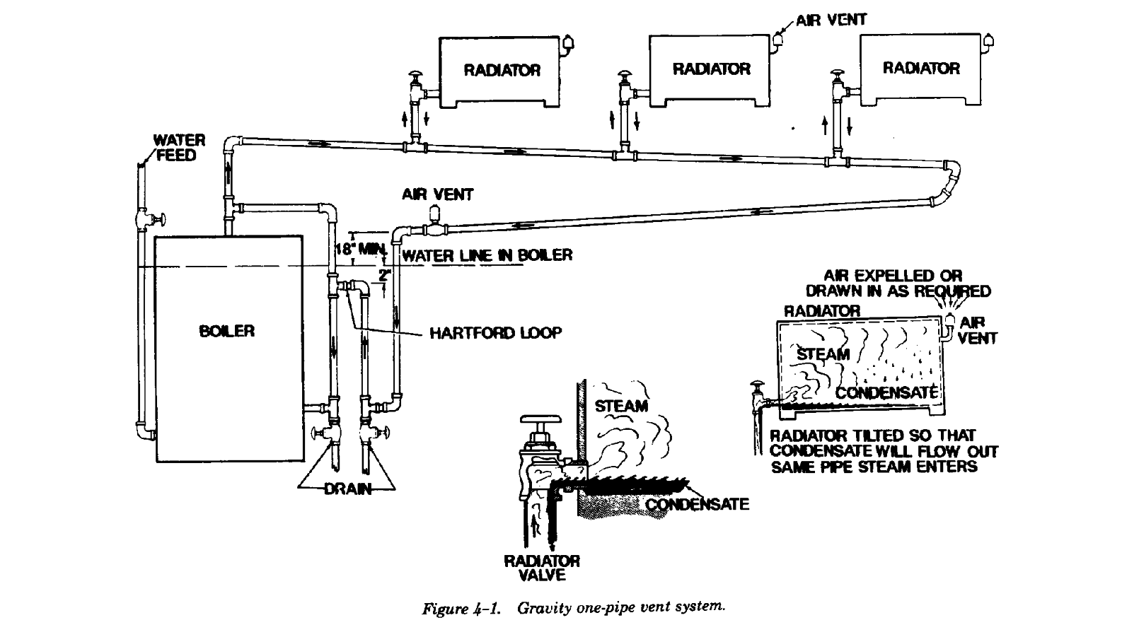
4-3. Gravity one-pipe air vent system.
Steam heating systems are classified according to
The gravity one-pipe air vent system was one of the
the method of returning the condensate to the
earliest types in use. Because the condensate is
boiler, whether by gravity or by mechanical means.
returned to the boiler by gravity, this system is
In the gravity system, the condensate is returned
usually confined to a single building. Steam is sup-
because of a static head of water in the return
plied by the boiler and is distributed through a
pipes. In this type of system all radiation must be
single piping system to radiators as shown in figure
above the boiler water line. In the mechanical
4-1. Return of the condensate is dependent on the
system, the condensate flows by gravity to a
hydrostatic head. Radiators are equipped with an
receiver and is then forced into the boiler under
inlet valve and an air valve. The air valve permits
pressure. The main difference between the
venting of air from the radiators and displacement
mechanical and the gravity systems is that radiation
by steam. Condensate is drained from the radiators
in the mechanical system can be located below the
through the same pipe which supplies steam.
boiler water line as long as there is a low spot to
which the condensate can be drained and from
which it can be pumped to the boiler, feed water
heater, or surge tank.
4-1
TM 5-642
a. Controls. Appropriate controls for this system
include a barometric draft control for boiler pres-
sure control, or a pressure stat which controls a
motor which operates the damper. Direct control of
steam flow by use of mechanically operated steam
valves is generally avoided due to difficulties in
removing condensate after shut-off, and also due to
the usual fluctuating steam pressure and flow
characteristics of the gravity system. The gravity
distribution system includes the boiler, radiators,
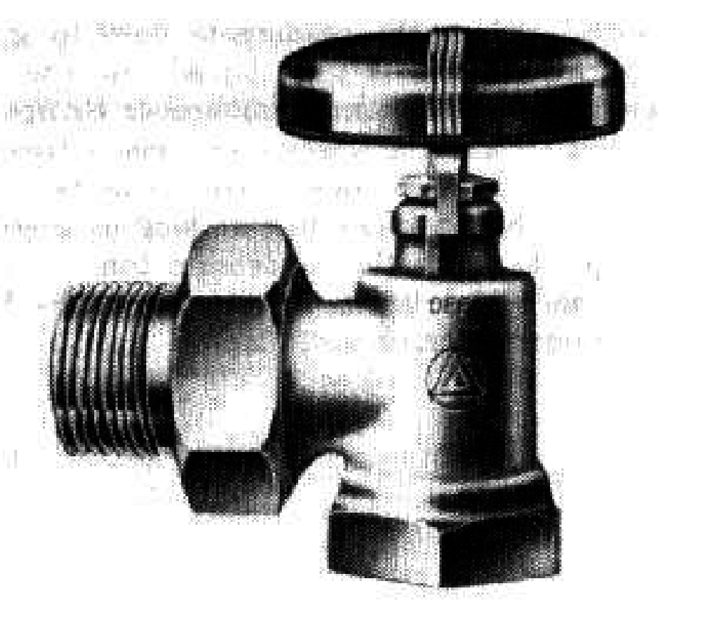
piping, angle radiator valves of the on-off type as
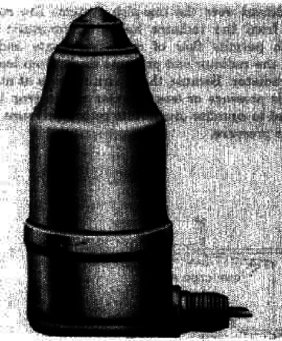
shown in figure 4-2, automatic air vent as shown in
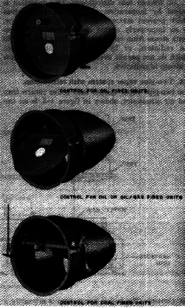
figure 4-3, and a barometric draft control as shown
in figure 4-4.
Figure 4-2. Angle radiator valve.
4-2
TM 5-642
Figure 4-3. Automatic air vent.
Figure 4-4. Barometric draft control.
b. Typical operating problems.
(1) Radiator heat failure. This is caused by air
binding as a result of plugged or defective air vents,
or by water logging due to insufficient radiator
pitch (toward valve) or to partially closed radiator
valves which permit trapping of condensate by the
partial vacuum created.
(2) Excessive noise. This is caused by air vent
failure and air binding of mains, insufficient radiator
pitch resulting in entrapment of water, plugged or
partially plugged wet return mains causing
condensate to back up into steam mains, or
improper pitch of mains and radiator branches.
(3) Fluctuating water line. This is caused by
excessive pressure drop in long mains and insuffi-
cient head between the end of the main and the
boiler water line to overcome the pressure drop.
Grease or oil in the boiler water will also cause a
fluctuating water line.
4-3
TM 5-642
(4) Uneven heat distribution. This condition is
provement over the one-pipe system. The return
caused by inoperative radiator air vent valves which
line from the radiator has a thermostatic trap which
prevent steam from entering the radiator, by an
permits flow of only condensate and air from the
improperly vented steam main which prevents
radiator and prevents steam from leaving the
steam from reaching the piping branches to the
radiator. Because the return main is at atmospheric
radiators, or by improperly pitched pipes which do
pressure or less, a boiler return trap is installed to
not permit even and uninterrupted flow of steam to
equalize condensate return pressure with boiler
radiators.
pressure.
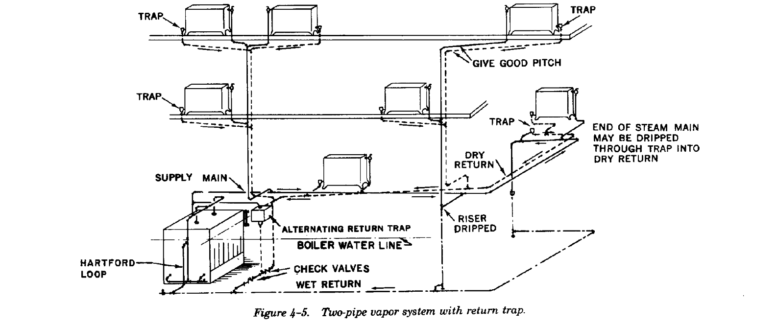
4-4. Two-pipe vapor system with return trap.
The two-pipe vapor system with boiler return trap
and air eliminator, shown in figure 4-5, is an im-
a. Controls. The boiler return trap is primarily a
usually air tight and can be operated at
double valved float mechanism which permits
subatmospheric pressures as low as 15 inches to 20
equalization of boiler pressure and pressure within
inches of water vacuum. This system is not used
the return trap. The boiler return trap is installed on
with unit heaters or blast coils which cause the
a vertical pipe in the return system adjacent to the
condensate to be returned in slugs and the rate to
boiler. The return trap has a valved steam
be variable. Appropriate controls for this type of
connection to the boiler header and a vent connec-
system are similar to those for gravity systems.
tion to an air eliminator. Condensate rises into the
b. Typical operating problems.
return trap when the boiler is under pressure; the
(1) Radiator heat failure. This is caused by
float-actuated vent valve is open during this part of
plugged or defective main air vents and by radiators
the cycle. When condensate reaches the trip level of
waterlogged due to insufficient radiator pitch
the trap, which is always below the bottom of the
toward return connection. Radiator heat failure is
dry return, the float actuated valves reverse. The
also caused by clogged radiator traps and center air
vent closes and the steam valve opens. This
binding due to steam entry from both the return and
equalizes pressure above the condensate in the float
supply ends if the trap is leaking because of failure
trap with that of the boiler and causes the
of the thermal element.
condensate in the trap to flow into the boiler. When
(2) System heat failure. This is caused by
low level is reached, the float actuated steam and
clogged or defective air eliminators or improper
vent valves again reverse. The steam valve closes
operation of return traps. Return traps must be set
and vent valve opens, relieves the pressure in the
level and have leveling tabs for proper installation.
trap, and again permits the condensate from the
Return trap floats usually actuate the valves
system to rise into the return trap. This system is
through a system of balanced weight arms which
4-4
TM 5-642
may develop incorrect adjustment. The two check
steam and the return flow of condensate equals the
valves at the base of the return trap must be in good
rate of steam generation. It is therefore necessary to
condition and the flow must be directed toward the
start a cold system with a slightly higher waterline
boiler. The air eliminator and vent valve mechanism
to provide for flow of condensate in the return
must be cleaned periodically to assure free action.
system and storage of condensate in the receiver.
The system may bind if excessive trap leakage
The high and low levels of the pump float valve
occurs.
setting should be set with adequate difference to
(3) Air eliminator failure. Water spurt from the
eliminate frequent pump cycling. The settings
air eliminator is caused by defective return trap
should, however, be close enough so that the
operation or by a clogged connection to boiler.
condensate discharge will not be large enough to
(4) Water line failure or fluctuation. This is
cause excessive changes in normal boiler water
caused by boiler pressure beyond the limit of the
level. Make-up water to this installation is supplied
trap, improper adjustment of the return trap, or
by manual feed or through automatic water feeders.
boiler water contaminated with oil or grease.
Automatic water feeders should be set at the
minimum safe boiler water level to eliminate
4-5. Two-pipe vapor system with condensate
unnecessary feed at low periods of the pump oper-
pump.
ating cycle. This pump control cycle is considered
The two-pipe vapor system with condensate pump
most satisfactory and results in little difficulty of
is similar to the two-pipe vapor system with air
operation.
eliminator return trap, except that the condensate is
(2) Waterline mounted float switch. With this
returned to the boiler by a power driven centrifugal
control method the float switch is mounted in a
pump instead of a return trap. The system includes
separate chamber with pipe connections above and
a separate main, radiators fed at the top, and a
below the boiler water line. Since the pump may
return system with thermostatically trapped outlets
start at periods when the pump receiver is not filled,
at the bottom of the radiators opposite the feed
a float controlled make-up water valve is connected
end. The return main terminates at the receiver of
to the pump receiver to maintain a minimum water
the condensate pump and all air in the system is
level in the receiver. This arrangement maintains a
vented through a vent on the receiver. With use of
water level which does not vary too much and
a condensate pump, all returns to the pump are dry
eliminates the lag of condensate feed described
and radiators may be located below the boiler water
above. Operating difficulties encountered with this
line; this is not possible in the systems previously
type of control usually more than offset the
described. Ends of steam mains are dripped and
advantages. The float switch located on the boiler
vented into the dry return main through
water line is a source of mechanical difficulty
combination float and thermostat (F&T) traps. The
because of its small operating level range. If the
two-pipe vapor system with condensate pump is
water line control is out of cycle with the
frequently adapted to relatively large installations,
condensate return from the system, considerable
particularly when unit heaters or blast coils are used
make-up is used and condensate is wasted through
and is probably the most practical and trouble free
the pump vent or overflow, unless there is surplus
system. In addition to the boiler pressure controls,
storage space in the receiver. The float operated
thermostatically controlled radiator valves or zone
receiver make-up valve is a source of unnecessary
control valves may be used, since the return system
make-up of raw water to the receiver. This pump
is considered to be at atmospheric or lower
control system is suited only for systems which do
pressure. This permits gravity flow of condensate
not return all of the condensate to the boiler. This
to the pump receiver.
would include isolated buildings for which return is
a. Controls. The condensate pump is normally
not practical or economical or installations where
controlled by a float activated switch located either
open steam jets are used, such as for dishwashers
in the condensate receiver or in a pipe located at
and steam tables.
the boiler waterline.
b. Typical operating problems.
(1) Receiver mounted float switch. When the
(1) Radiator heat failure. This is caused by in-
condensate from the system fills the receiver to a
operative traps or improper radiator pitch.
predetermined high level, the pump starts and, in
(2) System failure. This is caused by clogged or
turn, stops when a predetermined low level in the
closed air vents at the pump receiver, by flooding of
receiver is reached. Water between the two levels
the return due to improper cut-in of the pump or by
is discharged to the boiler. In this system, there is
lack of pump capacity. Steam or air binding of the
an initial lag in return of condensate. The boiler
system caused by leaking traps may also occur.
waterline lowers until the system has filled with
4-5
TM 5-642
(3) Overflow from receiver vent. This is caused
and air is discharged at the bottom of the opposite
by improper pump cut-in, inadequate pump capac-
end of the radiator through a thermostatic trap. All
ity, clogged discharge piping or failure of the check
returns are dry and terminate at the vacuum pump.
valve on the pump discharge pipe. Failure of the
The vacuum pump is usually motor driven,
check valve on the discharge side of the boiler feed
although low pressure steam turbines are
pump permits flow of the boiler water through the
sometimes used. The vacuum pump returns
pump and then to the receiver. The pump must then
condensate to the boiler and maintains a vacuum or
return the leakage to the boiler and this might be
sub-atmospheric pressure in the return system. The
beyond the capacity of the pump. Hot condensate
maintenance of a vacuum in the return system (3 to
or hot boiler water back-up may cause vapor lock
10 inches water gauge) enables almost
of centrifugal pumps and the pump will fail to
instantaneous filling of heating units at low steam
discharge to the boiler. Overflow will occur in
pressure (0 to 2 psig) since air removal is not
pumps in which float controlled make-up valves
dependent on steam pressure. This system is used
feeding the receiver are defective. This will cause
in all types of buildings and offers a definite
excessive make-up water feed and flooding of the
advantage for operation of indirect radiation units,
system.
heating coils and ventilating units, and for other
(4) Air returning to receiver tank and heating
units for which close automatic control is required.
system. It is advisable to provide a ball check or a
Quick filling of steam elements for this system is
vacuum vent for the air vent from the receiving
obtained since steam spaces are under vacuum
tank. This type of vent permits discharge of air
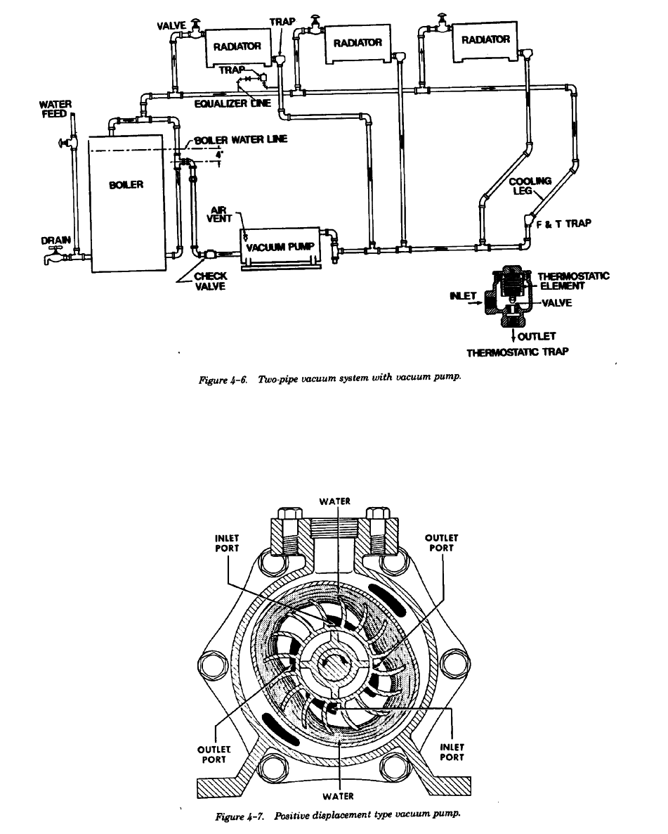
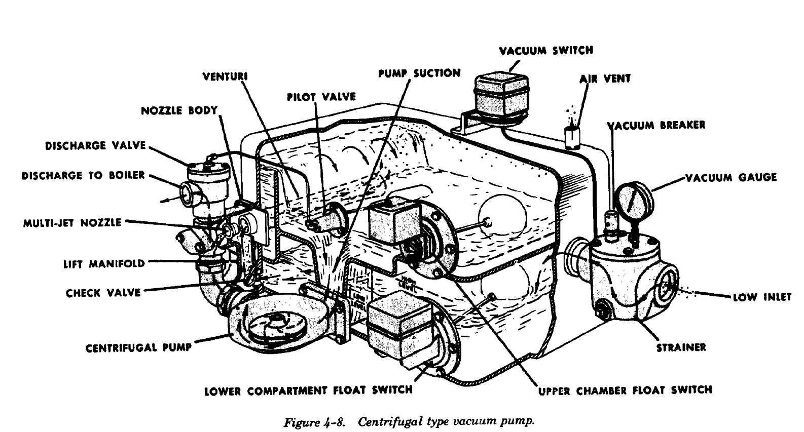
during periods of shut-off. Vacuum pumps are two
from the system and prevents return of air to the
general designs, positive displacement and centrif-
receiving tank and heating system. A vacuum of
ugal type. These are shown in figures 4-7 and 4-8.
from 1 to 5 inches water gauge can be created if the
Both types have a centifugal pump to return water
system is tight.
to the boiler. The vacuum pump withdraws air and
water from the system, separates air from water,
4-6. Two-pipe vacuum system with vacuum
expels air to the atmosphere and pumps water back
pump.
to the boiler. Usually the vacuum pump is equipped
The two-pipe vacuum system with vacuum pump
with a float switch as well as a vacuum switch and
shown in figure 4-6 is similar to the two-pipe vapor
can be operated as a condensate pump unit. The
system with condensate pump. The piping system
float switch should be used only when the vacuum
includes separate steam and return mains. Steam is
system is defective and then only until defects can
supplied at the top of the radiators and condensate
be repaired or corrected.
4-6
TM 5-642
4-7
TM 5-642
a. Controls. Controls for vacuum type heating
(2) System failure. This occurs when the
systems include boiler pressure control, vacuum
vacuum pump fails to clear the system of air. The
and float control for the pump, and may include
system may also fail because mains are improperly
appropriate types of thermostatic or pressure con-
pitched or trap failures allow excessive steam leak-
trolled shut-off or modulating valves for control of
age or water logging of steam mains.
heating elements.
(3) Overflow from pump vent. This occurs be
b. Typical operating problems.
cause of inadequate pump capacity; defective
(1) Radiator heat failure. This is due to defec-
valves, jets, or pump clearances; or stoppage in the
tive or clogged thermostatic traps or improper ra-
pump discharge connection to the boiler.
diator pitch.
Section II. BOILER TYPES
4-7. Cast iron boilers.
supply steam header is at the top center of the
In general, cast iron boilers are shipped in sections
boiler; the return headers are located laterally near
and assembled at the installation site. Small boilers,
the foundation. Heated water rises through the
however, are factory assembled and shipped as a
vertical sections from the return water headers, and
unit. Cast iron boilers are usually referred to as
steam is taken from the supply steam header at the
sectional boilers. Figure 4-9 shows a sectional cast
top of the unit. Cast iron boilers usually range in
iron steam boiler commonly used in steam heating
capacity from two boiler horsepower (1 boiler
systems. The unit shown is an independent header
horsepower equals 33,500 BTU/hr) up to 100
type, in which each section is actually an individual
boiler horsepower.
boiler connected to supply and return headers. The
4-8
TM 5-642
Figure 4-9. Sectional cast iron steam boiler.
a. Initial operation and cleaning
(d) Check for air leaks, particularly at the
(1) Checking. Prior to start up after a pro-
joint between sections and the base and between
longed shutdown, the complete installation should
the base and foundation.
be carefully checked. Follow the steps described
(e) Be sure that the make-up water and
below:
supply water piping is in good operating condition,
(a) Examine the combustion chamber and gas
condensate return equipment is properly connected,
passes; determine that all debris has been removed,
and that electrical connections are complete and
and check burners or grates, if applicable, for
properly fused.
proper operation.
(f) Determine the correct normal and low
(b) Check steam and return header-valves,
water levels. If the levels are not marked, place
gauge glass valves, and stop cocks for proper
permanent markings at suitable locations on the
action.
front of the boiler adjacent to the gauge glass or on
(c) Check the damper regulator and connec-
the frame work of the gauge glass. Manufacturer*s
tions (coal fired systems) and check draft dampers
literature should be used to determine the proper
for proper action.
water level.
4-9
TM 5-642
(2) Initial filling. Remove the pop-safety valve
radiators is accomplished in steps as suggested, the
and make a valved overflow pipe connection be-
boiler load will be relatively low and manual
tween the safety valve opening and a floor drain or
maintenance of the water line simplified. Open the
ground outside boiler room. Open the overflow
drain caps in the mains during this clean-out
valve and petcocks at the water line, then fill the
process, if convenient.
boiler until water overflows through the temporary
(g) A steam heating boiler and piping system
overflow. Close the water connections valve and
will not operate satisfactorily if oil or other
impurities are present in the system. Proper internal
open the drain allowing all water to run out of the
clean-out of the boiler and piping eliminates
boiler. Refill the boiler to the correct water level
unnecessary operating difficulties later. Do not
plus approximately two inches, then close the
connect the return system to the boiler until the
petcocks and remove the t