without shaft binding, the packing should be re-
enough to close the float switch.
placed. Provide proper drains from pump bases.
(9) Be sure all guards are in place before start-
(2) Packing replacement. Occasionally packing
ing the unit.
will require replacement because of normal wear or
b. After starting.
improper gland adjustment which causes drying or
(1) On low pressure units, adjust the vent pet-
burning. Use only soft, square, packing of proper
cock so that it is open just sufficiently to allow
size. Cut packing into rings which will fit snugly
escape of steam and air as rapidly as condensate
around shaft with ends just meeting. Be sure the
flows into the receiver.
ends are square. Remove gland nuts, take out gland
(2) See that motor rotates in proper direction.
halves and pick out old rings of packing. Clean the
(3) See that all pipe connections are tight.
shaft and packing box of dirt or sediment and insert
(4) See that the float switch starts and stops the
packing rings, pushing each succeeding ring back
pump at desired levels of water in the receiver.
into place. Stagger packing ring joint ends to
(5) See that the motor picks up speed quickly
ensure a good seal. Reinstall gland halves, bolts,
and maintains a constant rotation rate. If motor is
and nuts, and be sure that gland followers enter the
brush type, see that it does not spark profusely.
packing box to a depth of at least ‘/8 inch. Adjust
(6) Check the packing-gland adjustment.
the glands.
(7) Observe operation of the unit closely for 3
c. Shutting down. When shutting the pump unit
hours after starting and at regular intervals there-
down for any considerable period, open the motor
after. A new, properly operating pumping unit
disconnect switch. Drain the unit by removing drain
should be carefully watched to note its initial per-
plugs at the bottom of the receiver tank and pump
formance, for later comparison checks. Consult
casing until all water drains out. Never expose the
manufacturer*s instructions.
pump unit to freezing temperatures when filled with
water. Cover the motor and switches to protect
4-22.
Maintenance.
them against dust and moisture.
a. General.
d. Pump lubrication. Keep a regular lubrication
(1) At regular intervals lubricate the pump and
schedule and avoid both over and under lubrication.
motor as specified in lubrication instructions.
When oil lubrication is used, a good grade neutral,
(2) Maintain proper adjustment of the packing
medium viscosity, mineral oil is satisfactory. Grease
glands and change packing when deteriorated.
lubrication requires more careful lubricant selection,
(3) Keep the inside and outside of the motor
because there are a great many products from
and controls free of moisture, oil and dirt. If neces-
which to choose. The important factors in choice of
sary blow out their interiors with a bellows. If
grease for a pump are: its resistance to water,
switch contacts become corroded or pitted they
determined by the soap-base used in its
should be smooth and treated with a contact pre-
manufacture; and its consistency as related to
server or replaced. If the motor is of the brush type,
operating temperature and method of application.
replace the brushes when necessary.
Lime-soap-base greases are relatively insoluble and
(4) Wearing parts on centrifugal pumps, such as
non-emulsifying and should be used where water
bearings and wearing rings, are readily accessible.
may come in contact with the bearing. The higher
To get peak performance, check these parts at
the operating temperature, the heavier the grease
intervals depending upon severity of service, and
should be. Use only ball bearing lubricants for
replace worn parts if necessary.
grease lubricated ball bearings; never use graphite.
(5) To ensure the best operation of the unit
Lubricate the motor according to directions on the
make a systematic inspection periodically.
motor instruction sheet.
b. Packing boxes.
(1) Gland adjustment. Adjust packing glands so
4-23.
Typical operating difficulties.
there is a weep or slight leakage of water around
a. Pump fails to operate.
the shaft when the pump is operating. This is
(1) Fuse blown or thermal unit is tripped or
necessary for cooling and lubrication, and keeps
loose.
the packing in good condition. To adjust glands,
4-20
TM 5-642
(2) Shaft binding, or impeller blocked.
4-24.
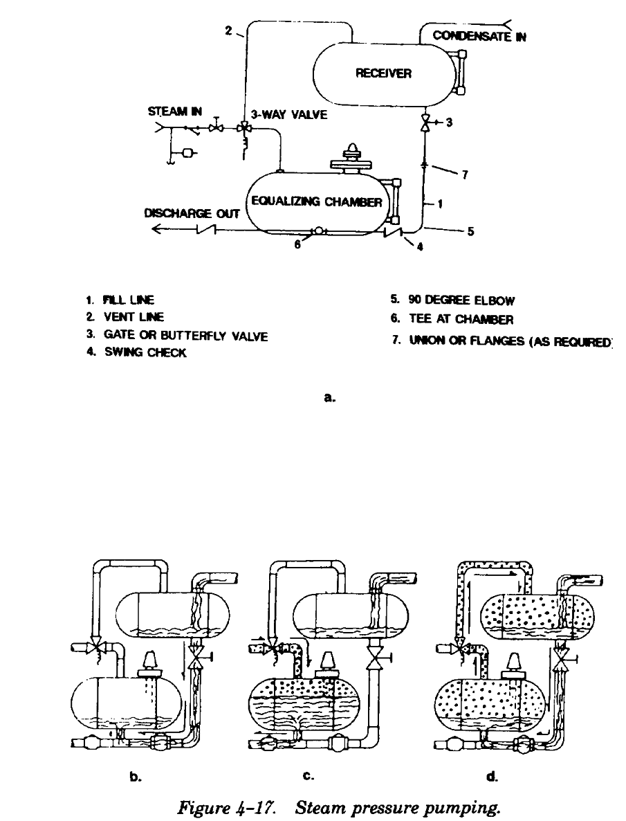
Steam pressure pumping systems.
(3) Switch contacts corroded or shorted, or ter-
a. General. This type of condensate handling
minal connections broken somewhere in circuit.
system is an energy saving, highly efficient way to
(4) Float control mechanism not functioning or
pump or lift liquids in many types of operations. It
float waterlogged.
is particularly suited for effectively handling con-
(5) Wiring hookup or electrical service provid-
densate from all types of heating and processing
ed is incorrect, or switches are not set for oper-
equipment. Instead of using motor driven pumps,
ation.
this system uses steam or other gases under pres-
(6) Motor is grounded or burnt, or brushes,
sure as the motive force. Unlike conventional con-
when present, are stuck or worn.
densate pumps, a steam powered pump can handle
(7) Electrical service or phase failure.
temperatures over 185 EF without the need for
(8) Receiver vent is not open.
venting or cooling. It requires no high maintenace
b. Fuses blown or thermal units trip.
stuffing boxes, motors or starters. It contains no
(1) Fuse rating used is incorrect.
revolving shafts and utilizes a minimum of moving
(2) Shaft is stuck or not rotating freely.
parts.
(3) Loose connection somewhere in circuit.
b. Operation. Figure 4-17 shows the operating
(4) Controls are worn or arcing.
cycle for one type of steam powered pumping
(5) Motor is grounded or partially burnt out.
system. Condensate from the equipment being
(6) Brushes, when present, are sparking pro-
drained enters the receiver tank and flows down the
fusely or sticking. Commutator is scored or brushes
fill line into the equalizing chamber (figure 4-
worn.
17(1)). When a predetermined high level is reached
(7) Motor is overloading.
in the equalization chamber, the level control
(8) Fuse or thermal unit location is too hot if
system sends out a signal which causes the 3-way
placed near boiler or flue.
valve to cycle. When this valve cycles, the vent line
(9) Short circuit in wiring.
is closed off and high pressure steam is admitted to
c. Pump runs continuously.
the equalization chamber. This steam pressure is
(1) Float is stuck in raised position.
confined above the condensate in the chamber and
(2) Float switch adjustment is improper.
its effect is to move the condensate out of the
(3) Switch contacts are burnt closed.
chamber and into the discharge line. When the
(4) Pump is “steam bound” due to very high
condensate reaches a predetermined low level, the
water temperature.
level control system sends another signal causing
(5) Discharge head is higher than anticipated.
the 3-way valve to revert to its original position.
(6) Motor speed is too slow or voltage low.
Residual steam remaining in the equalizing chamber
(7) Pump is defective or capacity too small.
will flow through the vent line into the receiver
(8) Receiver is dirty. Pump suction clogged.
enabling the pressures in the two tanks to equalize
(9) Vacuum in receiver is reducing discharge
with each other. When this is completed, flow of
head on pump. See that vent is open.
condensate from the receiver tank to the equalizing
d. Pump operates at slow or variable speed.
chamber will start again. The cycle then repeats
(1) Switch contacts are arcing.
itself.
(2) Loose connection in electric circuit.
(3) Low voltage, or phase failure in polyphase
electrical service.
(4) Motor is partially burnt or grounded.
(5) Motor brushes, when present, are worn,
stuck, or spring tension is weak. Commutator may
be corroded.
(6) Clutch is defective in single phase repulsion
induction motor.
(7) If shaft is binding, check for improper gland
adjustment, impeller rubbing, impeller clogged, or
a bent shaft.
4-21
TM 5-642
once the condensate reaches the predetermined
high level of the equalizing chamber. At this
moment the level control device sends a signal
causing the 3-way valve to actuate. This signal can
be electrical or pneumatic. When the 3-way valve
actuates, it closes its normally open port in the vent
line and opens its normally closed port in the steam
line.
(2) Equalization and discharge cycle. The
steam flow through the 3-way valve enters the
equalizing chamber at a point above the condensate
(figure 4-17(3)). The initial pressure in the tank
immediately begins to increase. Until tank pressure
exceeds discharge line pressure no condensate will
be discharged. This period is called the equalization
cycle and represents a small fraction of the
discharge cycle. As the tank pressure increases
above discharge line pressure, condensate flow
starts and will continue until the predetermined low
level is reached. At this time the level control
device sends a signal which allows the 3-way valve
to revert to its original position.
(3) Vent cycle. Several events take place during
the vent cycle (figure 4-17(4)). In its closed
position, the 3-way valve prevents high pressure
steam from entering the equalizing chamber, but its
normally open port will allow the steam used for
discharge to flow into the receiver through the vent
line. Until this steam pressure is equalized with the
receiver, no condensate flow will occur between the
two tanks because the residual pressure keeps the
fill line swing check closed. Condensate entering
(1) Fill cycle. When condensate from equip-
the receiver during discharge and vent cycles
ment being drained enters the receiver, it will also
remains in the receiver until the next fill cycle
enter the fill line connecting the two tanks (figure
begins.
4-17(2)). Since the 3-way valve is not energized, its
c. Troubleshooting. As with any troubleshooting
normally open port will allow both tanks to be
procedure, care should be exercised when disas-
pressure equalized through the vent connection.
sembling a pipe line, valve or other pressure fit-
Therefore, the flow of condensate is by gravity
tings. Steam and condensate lines should be valved
head only. Typically, gravity head is 1 to 3 psi.
off and initial inspection should be made to ensure
Therefore, it is important that friction losses be
that no residual pressure remains in the valved off
minimized. While filling is taking place there is no
section(s). This same care should be followed when
steam flow through the 3-way valve and no con-
working with the electrical components. A trouble-
densate flow into the discharge line. The check
shooting guide for steam pressure powered pump-
valve in the discharge line prevents back flow into
ing systems is in appendix C.
the equalizing chamber. The fill cycle is complete
Section VI. VACUUM PUMPS
4-25.
General.
complete with a receiver, separating tank, and
a. The usual vacuum pump unit consists of a
automatic controls mounted as an integrated unit
vacuum section which withdraws the air-vapor
on one base. There are also special steam turbine
mixture and discharges air to the atmosphere, and
driven units which are operated from the heating
a water removal unit which discharges condensate
system steam supply. Under special conditions such
to the boiler. The vacuum pump unit is furnished
as an installation where it is necessary to return
condensate to a high pressure boiler, auxiliary
4-22
TM 5-642
water pumps are supplied. In some instances
should drain to a receiver or flash tank through a
separate air and water pumps are used.
high pressure trap. The receiver should have an
b. For rating purposes, vacuum pumps are clas-
equalizing connection to a low pressure steam main
sified as low and high vacuum. Low vacuum pumps
and drain through a low pressure trap to the
are those rated for maintaining less than 5½ inches
vacuum return main.
of mercury vacuum in the system and high vacuum
pumps are those rated to maintain vacuum at or
4-26.
Installation.
above 5½ inches.
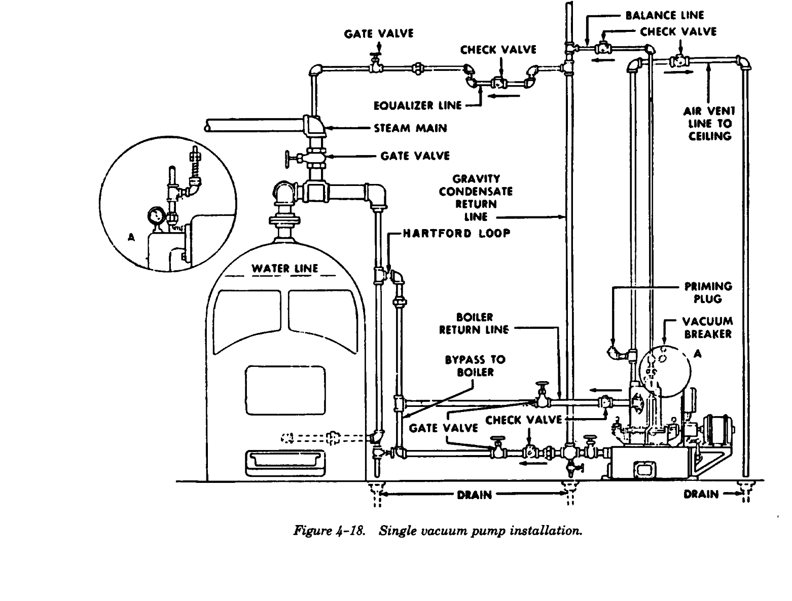
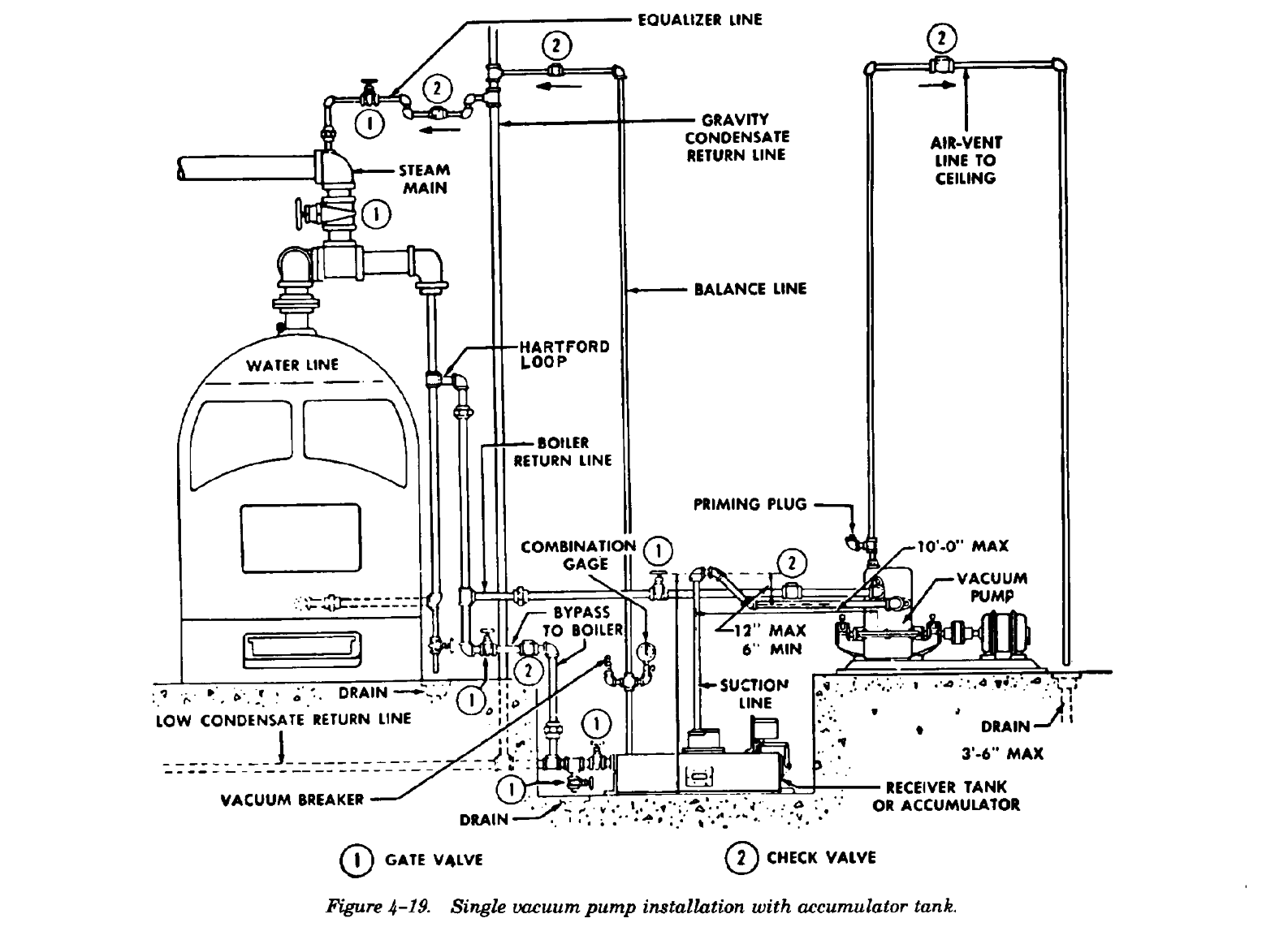
a. General. Figures 4-18 and 4-19 illustrate cor-
c. It is essential in vacuum installations that the
rect methods for installing vacuum pump units. In
entire system is tight in order to reduce the amount
connecting pipes to the pump or receiver, a union
of inward air leakage. Furthermore, it is essential
is included in each line as close as possible to the
that very high temperature steam is prevented from
unit for convenience in installation or repair. Pipe
entering vacuum return lines through leaky traps
stress upon the unit should be prevented. Pipes
and high pressure drips. The condensate from
used should not be smaller in size than their con-
equipment using steam at high pressure should not
nections on the unit and should be at least one or
be connected directly to a vacuum return line, but
two sizes larger if runs are long.
4-23
TM 5-642
b. Pipe connections.
(7) Pipes must be airtight and all steam traps
(1) A valved connection to a drain in the con-
must be of a suitable type, properly located, and in
densate return line is installed to permit draining or
good operating condition.
flushing of the system.
(2) A valved bypass from the condensate
4-27.
Controls.
return to the boiler return line is installed to
The vacuum pump is controlled by a vacuum regu-
permit operation by gravity in case of a power fail-
lator which cuts in when the vacuum drops to the
ure.
lowest point desired and cuts out when the vacuum
(3) The boiler return line is connected by
has been increased to the highest point. These
Hartford Loop.
points are varied to suit particular system or
(4) A receiver vent or equalizer line to a dry
operating conditions. In addition to this vacuum
vertical return riser is used to permit a continuous
control, a float control is included which automati-
flow of condensate into the receiver.
cally starts the pump whenever sufficient conden-
(5) An air-discharge vent line with a horizontal
sate accumulates in the receiver, independent of the
switch check valve is run up to a point as close to
amount of vacuum in the system. A selector switch
the ceiling as possible and back down to a drain.
is usually provided to allow the vacuum pump to
(6) A dry equalizer line between the condensate
operate as a condensate pump. This operation takes
return line and steam header, including a gate valve
place on float control and when vacuum control is
and tight seating check valve, is used to equalize
in the off position. The selector switch also
boiler vacuum when steam is shut off and to permit
provides manual or continuous operation when
normal return of condensate to pump receiver.
desired. A fused motor-disconnect switch is always
4-24
TM 5-642
provided in each motor circuit. Exclusive of
return line and running pump on float and vacuum
continuous duty models, all standard vacuum
control. Observe the operating time necessary to
pump units are furnished with automatic controls
create the vacuum for which the pump is set.
necessary for requirements of the motor furnished.
(4) Open the gate valve on the condensate
A float switch governed by the water level in the
return and check the time required for the pump to
receiver and a vacuum regulator controlled by the
create a vacuum in return system, keeping in mind
vacuum in the system are provided. In addition, all
that in large systems a reasonable period may
vacuum pump units have a three-way selector
normally be necessary.
switch for choice of continuous operation,
(5) Check the packing boxes for proper leak-
operation with float and vacuum control, or
age.
operation with float control only. This permits,
(6) After the pump is in operation, clean the
among other things, cutting out the vacuum regu-
inlet strainer as required by the manufacturer*s
lator when vacuum is not required.
instructions.
4-28.
Initial operation and cleaning.
e. Vacuum regulation. Regulate the pump to
create the vacuum desired by adjusting a spring
Piping systems may contain considerable quantities
tension nut in the vacuum control switch according
of scale, grease, dirt, or metal shavings. To protect
against damage from foreign material, the heating
to directions given in the switch instructions. The
system should be operated for 2 weeks with the
normal range is from 2 to 6 inches of mercury
condensate return line open to a waste drain before
vacuum.
the pump is first put into operation.
f.
Vacuum breaker valve. The vacuum breaker
a. Before starting Check the following items
or relief valve is usually set to open at 10 inches of
before starting the unit.
mercury and is adjusted by regulating the tension of
(1) Be sure the pump and motor have been lu-
the valve spring. The relief valve ordinarily requires
bricated as indicated by the manufacturer*s lubri-
no special care. It is used to relieve excessive
cation instructions.
vacuums that might result when float control is still
(2) Turn the shaft by hand to see that it rotates
activated after the desired vacuum has been
freely.
created.
(3) See that the characteristics of voltage and
g. Selector switch. Selector switches provided
frequency on the motor nameplate coincide with the
on vacuum pump units with automatic control have
electrical service provided. Check to see that all
three positions for pump operation marked Contin-
thermal units are “set” for operation.
uous, Float and Vacuum, and Float Only. Properly
(4) See that the drain valve is closed and all
necessary line valves open.
handled, this feature permits a flexibility of oper-
b. Priming the pump. Most vacuum pumps must
ation yielding both economy and effective pump
be primed before the pump is put into operation. To
performance. A few recommendations for operation
do this, remove the priming plug which is on the air
of the selector switch are given below:
vent line just above the pump and pour clean water
(1) “Continuous”. The pump will run continu-
through the elbow fitting into the pump casing.
ously independent of float or vacuum switches.
Replace the plug.
This mode of operation is used:
c. Starting the pump. Set the selector switch for
(a) To run the pump continuously for trial
float and vacuum control, or continuous operation,
test, or under unusual service conditions.
and close the motor disconnect switch.
(b) To ensure rapid heat-up in the morning.
d. After starting pump. After the pump has been
started check the following items.
(2) Float and vacuum. Pump operation is gov-
(1) See that the shaft rotates in the direction
erned by either vacuum regulator or float switch.
indicated by the rotation arrow on pump. Vertical
The pump operates when water is accumulated
units rotate clockwise looking down the motor.
beyond a set level in the receiver tank or when
Horizontal units rotate clockwise looking at the
vacuum in the return system falls below the mini-
pump from the motor end.
mum setting. The pump should be operated at this
(2) On larger units, check the flexible coupling
position for normal and heavy duty.
connection of the pump and motor shafts, and note
(3) “Float only.” The pump is governed by the
if the pump is noisy. If so recheck for improper
float switch only and the pump operates when
alignment or clearance.
return condensate in the receiver rises above high
(3) Check pump operation and control adjust-
water level. Operation is independent of the
ment by closing the gate valve on the condensate
4-25
TM 5-642
vacuum control switch. Do not operate the pump at
(4) Check stuffing boxes for proper packing
this position unless conde