Chapter 3
Site Planning
3-1. General.
Site planning:
a. Determines appropriate and required activities and their functional relationships through program analysis.
b. Evaluates the site through site analysis.
c. Establishes the organization of activities and facilities on site through the concept development of spatial relationships diagrams.
3-2. Program Analysis.
Program analysis translates user needs into physical criteria requirements for facilities. The program is the basis of the functional relationships diagram. The functional relationships diagram delineates the optimal relationship among activities and facilities. Both the user mission and project requirements will be verified by interviewing the user to determine the current status, AR 415-15 provides guidance on program analysis.
a. User Mission. The goals and objectives of the user mission will be reviewed. How the proposed project is intended to accomplish or support these aims will be defined. The user’s specific needs will be determined for the following:
(1) Functional requirements.
(2) Creation of organizational efficiency and safety.
(3) Relationship to adjacent functions.
(4) Contribution to the quality of life of the occupants.
b. Project Requirements, Accurate project requirements are fundamental to organizing and locating project elements on site. Failure to anticipate true programmatic and spatial needs can create many problems. This is especially true on small or confined sites. The program and space requirements will be fully articulated beyond the primary facility or building.
(1) Primary Facilities. The principal functions occurring at the facility and the necessary space requirements will be determined. If applicable, the Department of the Army (DA) facility standardization program definite designs will be used. Other items to be determined include the following:
(a) Probable points of ingress and egress and need for control.
(b) Special architectural configurations.
(c) Physical and visual connections to other facilities.
(d) Desired visual presentation.
(e) Use and desired proximity of shared facilities (e.g., dining halls or headquarters buildings.)
(2) Support Facilities. Program and space requirements will be determined for:
(a) Buildings. The guidelines for primary facilities will be followed.
(b) Utilities. The necessary types of systems (water, sewer, electric, gas, communications, etc.) will be determined. The location and capacity of available trunk lines will be identified. Probable sizes and loads will be estimated. Potential environmental controls (e.g., Environmental Protection Agency sewage outflow standards) will be discussed. Civil, mechanical, electrical and other appropriate engineering disciplines should be consulted.
(c) Outdoor Space. The need for outdoor space will be established. This includes active use areas (e.g., formation grounds or outdoor classrooms), active recreation (e.g., playing fields or tennis courts), and passive recreation.
(3) Circulation. Both the user and the Director of Engineering and Housing (DEH) should be interviewed to obtain information and data. The user will determine the number and kinds of vehicles. Transportation and traffic engineers should also be consulted as appropriate. Military Traffic Management Command (MTMC) provides detailed information on transportation and traffic concerns. Programming for circulation will cover requirements for access and on-site circulation, estimates of the type and quantity of parking demand, evaluation of alternative modes of travel, and the need for a site traffic impact study.
(a) Design Requirements. The design vehicles (passenger car, delivery van, truck, tracked vehicle, etc.) expected on site will be identified and listed. Design requirements for site access and on-site vehicular circulation are usually determined by the largest design vehicle on the list. Probable service requirements such as delivery (including loading docks), maintenance, sanitation, and emergency will be identified. Probable requirements for site lighting levels will be determined. Chapter 6 provides more specific design criteria for vehicular circulation and parking.
(b) Parking Demand. The user will determine parking demand, or number of required parking spaces, for non-organizational or private occupancy (POW vehicles and for all other vehicles (motorycles, trucks, recreational vehicles, etc.). The user will determine the types of parking spaces (e.g., visitor or employee) and the number of spaces per type. The need for separation of parking areas and any locational requirements (e.g., near the facility’s front entrance) will be identified. Peak (or highest) use hours for parking will be identified to determine the potential for shared parking with other facilities. Parking structures may be considered in areas of dense development, limited available land, and high parking demand (more than 500 spaces) by one or more facilities. Because structures are expensive to build and maintain, all of the above criteria should be met to make a structure economically feasible.
(c) Alternative Travel Modes. Because parking consumes enormous space and typically dominates the landscape setting of facilities, alternative modes of travel to the site and carpooling should be encouraged. The impact of installation transport systems (e.g., bus routes and pedestrian and bicycle paths) will be determined.
(d) Site Traffic Impact Studies. The need for a site traffic impact study is determined by the condition of the site’s accessibility and the traffic volume projected to be added to adjacent roads. Appendix B provides an outline for a typical study report.
(4) Physical Security. The functional requirements of the user will determine the requirements for physical security. The Provost Marshal or Physical Security Officer will be interviewed concerning security needs. Additional help may be obtained from security engineers and/or physical security specialists. Requirements for physical security deal with protective measures to mitigrate the threat from a variety of tactics. The threat is determined through a threat analysis which should be done during project planning. Physical security includes the following site considerations and needs:
(a) Facility setback from roadways, parking areas, the site perimeter, other facilities and other use areas.
(b) Proximity between primary and support facilities.
(c) Physical barriers to prevent or delay unauthorized pedestrian and vehicular access and to resist weapons and/or explosives effects.
(d) Entry control points.
(e) Visual seclusion or openness.
(5) Noise Abatement. The need to maintain an acceptable noise level within the primary facility or to prevent the noise level of the primary facility from impacting the surrounding area will be deter mined. TM 5-803-2 provides guidance in planning for noise abatement.
(6) Future Expansion. Planning for future expansion which is neither programmed nor prioritized in the master plan can be a problem. Often, it takes place in a casual manner, depending upon whether the user raises the possibility. The facility’s potential for future expansion should be addressed. Future expansion may refer to actual physical expansion or increased usage of the primary facility. This is often difficult to predict and more difficult to estimate. A recommendation for expansion may be based on generally accepted growth trends for various user requirements. If it is anticipated, or simply desired, that the project expand at a later date, some estimate of growth should be made. Future expansion of circulation, including parking, should be considered.
c. Functional Relationships of Army Units. Functional relationships describe the need various activities and facilities have for mutual support. In planning, support can be operational and/or physical. Functional relationships diagrams graphically represent the necessary support. Program analysis serves as the basis for functional relationships diagrams. It relates the individual project to the larger context of the installation. It also organizes the activities and facilities within the project.
(1) Functional Relationships for a Brigade. Army planning is based on a series of relationships among a hierarchy of units: garrison, division, brigade and battalion. Functional relationships within one Army unit ideally should not interrupt those of another unit. However, organization of the relationships should allow for interaction and support among units as needed. A functional relationships diagram helps determine the need for such interaction and support. The diagram later helps place facilities where they can support the larger mission and helps locate shared facilities. Figure 3-1 illustrates a functional relationships diagram for a brigade.
(2) Preparing a Functional Relationships Diagram. Developing functional relationships is a method of organizing activities or facilities into ideal arrangements, based upon their interdependence. In site planning, this is expressed as the need for physical and/or visual connections. In turn, the connections become the basis for circulation patterns. A functional relationships diagram is a bubble diagram. It places proposed activities and/or facilities, including circulation, in the ideal arrangement for efficiency, safety and convenience. The diagram delineates the best locations for facilities in relation to each other, irrespective of site considerations. It does not consider any site
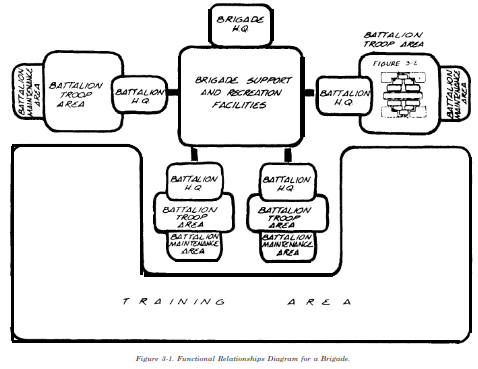
but forms the basis for site design. As the number and complexity of activities and facilities increase, a variety of alternatives should be explored and compared to find the optimal arrangement. Diagrams should be drawn at an appropriate scale to accurately represent the proposed spatial requirements of the facilities and circulation. A diagram may be developed through the following steps:
(a) Delineation of the approximate square footage of the primary facility in a bubble or block.
(b) Delineation of the approximate square footage of support facilities into bubbles or blocks and their placement in relation to the primary facility.
(d) Delineation of major vehicular access and circulation with weighted lines. Arrows should be used to indicate access points and direction of traffic flow.
(d) Delineation of major pedestrian access and circulation with weighted lines and arrows.
(e) Delineation of future facilities and circulation with dashed lines.
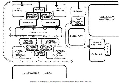
(3) Functional Relationships for a Battalion. The importance of functional relationships within an Army unit is determined by operational requirements. Tabulation of Equipment units are planned for in land area by battalion size. Figure 3-2 illustrates a functional relationships diagram for a battalion complex. It shows an optimal arrangement of the areas listed below. The diagram shows both vehicular and pedestrian circulation and delineates future expansion. The functional areas of a battalion are:
(a) Battalion headquarters and classroom.
(b) Headquarters parking area.
(c) Battalion recreational facilities.
(d) Battalion maintenance area.
(e) Company administration and supply.
(f) Company service area.
(g) Company troop barracks.
(h) POV parking area.
(i) Formation area.
(j) Facilities shared with other battalions or companies.
3-3. Site Analysis.
Site analysis inventories onand off-site conditions and evaluates how these conditions may impact the project. The principal elements of the evaluation are translated into a written and graphic summary of opportunities and constraints. Complete documentation of the inventories and evaluation are important since they may be accomplished by personnel other than those who later do site design. A thorough site analysis is fundamental to responsive and responsible site design. It is important to understand the potential impact various site elements can have on a project. It is important to know how these elements interrelate and are impacted by changes to each other. The involvement of different disciplines, as appropriate to the site, is essential to understanding these relations and to preparing a sound analysis.
a. Site Reconnaissance. Site reconnaissance deals with the acquisition of site information.
(1) Sources of Information. Sources include installation personnel and documents, especially the installation master plan. Past project plans and reports also provide information. Site-specific topographic and geotechnical surveys should be acquired prior to site reconnaissance.
(2) Site Survey Map. The topographic survey is the foundation of the site survey map. It should be acquired as soon as practical for any project. The site survey should locate all existing above and below-ground facilities and structures. It should show information about area boundaries and size, topography, water bodies, drainage patterns, utilities, roadways, vegetation and other site features.
If additional information is needed, other mapping resources include aerial photographs; installation documents; and US Geological Survey (USGS), Soil Conservation Service and Federal Emergency Management Agency (FEMA) maps. FEMA maps provide information on flood plain water surface profiles and flood plain outlines.
(3) Site Visit. A site visit is essential to developing an accurate site analysis. No other task provides as much useful information. A site visit provides the opportunity to:
(a) Verify existing information, especially if a current topographic survey is not available.
(b) Evaluate the impact of existing onand off-site conditions.
(c) Discover previously unknown conditions and factors.
b. Site Inventory and Evaluation. A site inventory documents all existing conditions, both onand off-site. It evaluates the impact they will have on site development. The evaluation may be simply a positive or negative assessment or may be rated on a scale. The data collection procedures for master planning, as described in TM 5-803-1, provide a useful start for preparing site inventories. The site survey map serves as the base map for the inventory. The information may be compiled on one or a series of maps, depending upon the size and complexity of the site. Usually, off-site conditions are recorded on a single map at a scale which addresses sufficient area surrounding the site. On-site conditions usually require more than one map. These maps often reflect a combination of conditions which can be expected to affect each other (e.g., soils and geology, drainage and topography, or climate and vegetation). The overlay/ composite method registers a series of maps to a base map, allowing one map to overlay another. This method helps visualize how various conditions impact or reinforce each other.
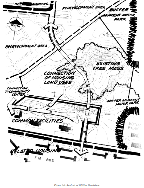
c. Off-site Conditions. Site analysis should extend beyond the project boundaries. Most off-site conditions are related to man-made features and activities. A site may be influenced by numerous factors (traffic, noise, light, visual conditions, drainage, etc.) which occur in the surrounding area. Both existing and future conditions should be considered. Figure 3-3 illustrates an analysis of off-site conditions for a candidate site for a battalion complex.
(1) Surrounding Land Use. Surrounding land use should be recorded on the analysis of off-site conditions map. It will be verified that the candidate site for the proposed project is located in an appropriate land use area according to the master plan. TM 5-803-8 provides further guidance on surrounding land use.
(2) Transportation. All existing and proposed transportation systems to and around the site will be evaluated for their accessibility. The primary and secondary roadways will be examined to determine potential access points, traffic loads and safety conditions including potential hazards. Underutilized parking areas available for shared use will be identified. Bus routes and loading zones convenient to the site will be identified. Pedestrian and bicycle paths which may be connected to project development will be identified.
(a) Site Traffic Impact Analysis. Site traffic impact analysis examines existing and future offsite traffic on adjacent roadways. It analyzes proposed on-site traffic. The principal purpose of the analysis is to determine the proper location and design of site access. Appropriate access location and design avoids: inadequate access capacity, congestion on site or on adjacent roadways, high accident rates, and limited potential for adjusting design or operation according to changing conditions. Site access should not interfere with traffic movement on adjacent roadways. Inappropriate access location and design can create as many or more problems as the increase in traffic volume. Projects may require off-site improvements to accommodate new traffic movement and additional volume.
(b) Site Traffic Impact Study. A site traffic impact study should be prepared for projects located near highly congested areas, high accident locations, and sensitive neighborhoods. The need for a study may also be established using the following threshold: the project is anticipated to generate 100 or more new peak direction trips to or from the site in the hour of peak traffic on the adjacent roadway(s). A transportation plan should be prepared for facilities which can be anticipated to expand and generate more than 500 peak hour trips. (Peak refers to the greatest number of vehicles moving in a specific direction and/or at a certain time.) The plan should be prepared for the horizon year (or final year of development) if the full buildout will be significantly larger. Data regarding the direction and time of peak traffic flow may be available on the installation. Trip generation rates most often used in traffic studies can be found in the report Parking Generation prepared by the Institute of Transportation Engineers. Guidance for determining trip generation can be found in Transportation and Land Development. Because a number of variations can occur when developing trip generation data for a specific site, transportation and traffic engineers should be consulted. If a site traffic impact study is needed, Transportation and Land Development provides further guidance. A minimum site traffic impact study should include information about: trip generation and design-hour volumes, trip distribution and traffic assignment, existing and projected traffic volumes, capacity analysis, traffic accident analysis, and the traffic improvement plan. Appendix B provides an outline for a typical study Report.
(3) Utilities. All utility systems which may be tapped for use will be located and their capacities indicated. If an existing system is running at or nearing its capacity, additional growth in the area may require improvements to the utility trunk line beyond the immediate site. Underground pipe line systems (e.g., fuel oil) will be located. Information useful in evaluating utility systems is their availability and reliability and the distances from existing trunk lines to the site. Utility analyses available from DEH should be acquired. The following systems will be identified and their sizes indicated:
(a) Water system with locations of fire hydrants near the site.
(b) Sewer system.
(c) Storm drainage system with invert elevations near the site.
(d) Electrical/gas system.
(e) Telephone system.
(f) Other types of communication systems.
(4) Environmental Conditions and Hazards. Environmental conditions and hazards near the site will be examined, beginning with a review of the environmental assessments prepared for the installation and the site. Storm drainage patterns, indicating direction of flow, will be located. Stormwater management areas which include the site will be located. Floodplain areas, wetland areas and wildlife habitat areas (especially for threatened and endangered species) will be identified.
The location of buried tanks will be identified. AR 200-2 and AR 415-15 provide further guidance on determining and evaluating environmental conditions.
(5) Historic and/or Archeological Resources. Archeological or historic sites protected from development will be located. Regulations governing activity near them will be identified.
(6) Safety Hazards. Requirements and distances necessary for fire codes, flood damage control, airfield and helicopter clear zones, and explosives safety from surrounding areas will be considered.
(7) Physical Security. Such physical security factors as the proximity of uncontrolled public use areas or vantage points from which standoff attacks could be launched will be considered if the threats to assets within the facility dictate concern. If the threat includes the use of explosives, the likely impact of collateral damage on nearby facilities will be considered.
(8) Sources of Air, Noise and Light Pollution. Immediate sources of pollution will be identified and their impact upon the site will be evaluated. Information may be found in the environmental impact assessments for the site and installation. The need and potential for achieving mitigation will be indicated.
(9) Visual Context. The site’s viewshed (area of visual enclosure) will be located if it extends beyond the site boundaries. The degree to which the surrounding area contributes to the site’s sense of enclosure or openness, creates desirable or undesirable views from the site, contains visible scenic features, or may need to be buffered from the site’s own visual condition will be defined.
d. On-site Conditions. On-site conditions include any existing factors which may affect development, either positively or negatively. They include both natural and man-made factors but usually emphasize the natural. Natural conditions are interwoven. Changes in one factor and location of the environment often create changes in other factors and locations. Although all detailed engineering data may not yet be available, site analysis looks for conditions which would prevent development of a facility, reduce the acceptable size or density, or create costs prohibitive to construction. Site analysis also looks for situations which can be used to reduce construction costs, reduce environmental damage, and create a more aesthetic site design.
(1) Geology. Geology influences the placement and design of facilities and activities on site. Typical soils data is available from the Field Operating Agency. Soil borings are required for each project. The following conditions may create problems and additional costs:
(a) Poor stability including limestone voids which do not support construction; layered deposits which must be considered before placing structures, regrading, or changing the moisture content of the soil; expansive substrates which can crack foundations, paving and other structural elements; and an unstable angle of repose which can limit regrading.
(b) Shallow depth to bedrock.
(c) Poor substrate strength which influences the size, depth and spacing of building supports and the structural grid above ground.
(d) Substrate drainage which can compound problems of slope stability and increase groundwater.
(e) Seismic factors (e.g., earthquakes and geologic faulting) which impact structural design.
(2) Topography. Topography will be examined to determine the various slopes on site. Slopes, to a large extent, influence the type of development and support systems a site can sustain. Slopes are usually placed in categories. The categories describe potential problems, suggest types of suitable development, and indicate the amount of grading which will accommodate development. Topographically responsive buildings accommodate steeper slopes with their size and/or structural foundation. These buildings can lessen the need for regrading. Figure 3-4 illustrates slope categories. Generally, grading can be described by the following categories:
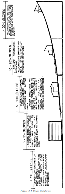
(a) Minimal: removing topsoil and establishing finished grade with only a minor transition between existing grade and constructed facilities.
(b) Moderate: requiring cuts and fills greater than one foot in more than 50% of the constructed site.
(c) Massive: requiring cuts deep into subsurface material and/or rock together with fills which cover the entire building or site area. The transition between existing grade and constructed facilities occurs at maximum slopes.
(3) Hydrology.
(a) Subsurface. Subsurface hydrology deals with the storage and movement of groundwater through aquifers. Subsurface information may be obtained from USGS maps. Increasingly, Federal, state and local agencies regulate the quantity and quality of water allowed to infiltrate the ground surface. Shallow, perched and fluctuating water tables can all impact development. If a site is in a groundwater recharge area, there may be restrictions upon the amount of impermeable surface and upon the minimum water quality allowed for infiltration.
(b) Surface. Surface hydrology, or runoff, increases as development decreases the area of infiltration. Surface conditions affecting site design are existing drainage patterns, flood plains, and man-made structures (e.g., dams or channelized drainageways.) Where soils are naturally subject to erosion and sedimentation, care may be necessary to avoid increasing slopes, concentrating runoff, or increasing impermeable surf