Chapter 4
Site Design Guidelines
4-1. General.
This chapter addresses the treatment of various natural and man-made elements when designing a site. The objective of site design is to place facilities on site with the least disruption to the natural environment. Site design emphasizes optimal use of site elements to enhance facilities. Just as the natural environment is woven from various elements, site design interweaves natural and man-made elements to achieve the optimal condition. While demanding a comprehensive knowledge of generally accepted practice, site design requires a flexible approach to problem-solving. The following factors should be considered in site design:
a. Siting and orienting buildings.
b. Developing vehicular and pedestrian circulation systems.
c. Providing adequate grading and drainage.
d. Responding to climatological conditions.
e. Locating utility systems.
f. Developing lighting coverage.
g. Providing for physical security.
4-2. Building Location.
The location of the primary facility is key to a successful site design. The building is usually the most prominent single element and the center of site activity. This does not mean that it belongs in the middle of the site. Several factors influence building location. Siting effects a compromise among the following factors:
a. Dimensional Factors. The building dimensions or footprint, the desired promixity to other facilities, buffer zones, spacing standards, and setbacks influence building location. These distances, especially those established for safety purposes, usually must be rigidly maintained.
(1) Buffer Zones. Buffer zones may involve such requirements as screening or absence of vertical elements. Buffer zones maintain mandated distances for:
(a) Runway clearances.
(b) Noise abatement.
(c) Security threats.
(d) Storage of hazardous materials.
(2) Spacing Standards. Spacing between buildings is normally determined by their:
(a) Functional relationships.
(b) Fire separation requirements.
(c) Physical security requirements.
(d) Need for future expansion of either or both facilities.
(e) Need for passive and active open space for the facility.
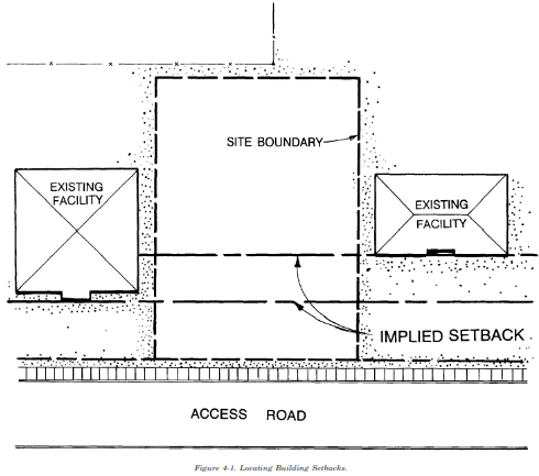
(3) Setbacks. Setbacks are the distances between buildings and property frontages, roadways, parking areas and other buildings. Building setbacks may be established by the installation design guide or by historic usage. If building setbacks have been established in an area, these setbacks should be observed. Where setbacks are not established, new buildings should be located in relationship to the surrounding structures. Figure 4-1 illustrates an implied setback area between two existing structures. A new building should normally conform and align with the front of one or other other building. It should not be placed in front of the foremost structure, behind the rear structure, or in the middle space between the two structures.
(4) Proximity to Other Facilities. A building’s relationships to its support facilities and to other primary facilities influence its location. Proximity to access roads, existing utility lines, and other compatible functions (especially if they share facilities or have interdependent activities) also influence location. When a building is a shared facility, it should be centrally located and within a reasonable distance from all participating users. Buildings which depend upon a shared facility should acknowledge this relationship by orienting either the front building face or a doorway area towards the shared facility.
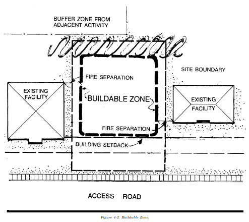
(5) Buildable Zone. Using the guidelines above, a development perimeter can be developed. This perimeter quickly defines a buildable zone as shown in figure 4-2.
b. Environmental Factors. The location and condition of such elements as geology, soils, drainage and vegetation may create areas which should be excluded from development. This further defines the buildable zone. Such areas:
(1) Are unbuildable for structural, economic or environmental reasons.
(2) Require protection from construction activity.
(3) Require preservation of their natural integrity.
c. Orientation. Building location may be influenced by orientation for the purpose of energy conservation.
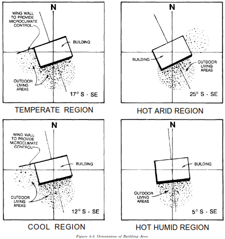
(1) Solar. Buildings should be oriented to take advantage of passive solar heating and cooling conditions. The solar study determines orientation. Generally, the long axis of a building is oriented along or at some angle less than 45 degrees to the east-west axis. As illustrated in figure 4-3, this orientation allows facilities to do the following: breezes.
(a) Harvest or avoid maximum sunlight.
(b) Be protected from northern winds.
(c) Take advantage of east-west summer
(d) Create shade to the south.
(e) Locate outdoor living spaces in the more comfortable southern area.
(f) Create microclimatic pockets, as appropriate, to the east or west of the building.
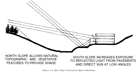
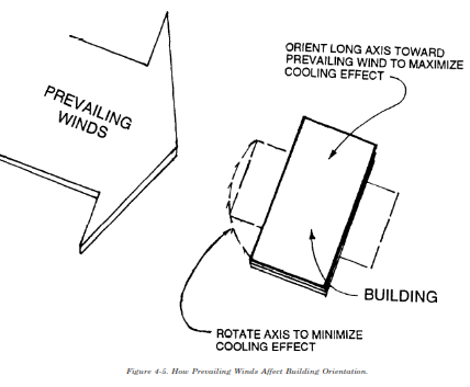
(2) Other. Other site-specific conditions can influence building alignment. Figure 4-4 shows how slope orientation may impact the sunlight and subsequent heat a building receives. Slope orientation may increase exposure to the sun or may, in combination with structures or vegetation, create pockets of shade. Figure 4-5 illustrates how building orientation may be modified to take advantage of or reduce the impact of prevailing winds. Existing topography and vegetation can also create microclimatic pockets. These pockets alter normal weather conditions by reducing available sunlight, creating shade and reducing prevailing winds.
d. Visual Determinants. Visual considerations for siting buildings are determined by both the user’s needs and existing conditions. A building may need to be clearly visible from the access road. The user may desire a visual relationship between structures which are located within a single unit and/or service the same user group. In these circumstances, the locations of entrances are often important. Their visibility may be used to reinforce circulation. Existing conditions which can influence building location include:
(1) Views into areas of good natural quality.
(2) Views which can be achieved by taking advantage of higher site elevations.
(3) Visual enclosure which can be provided by existing topography and/or vegetation.
4-3. Circulation.
Circulation should promote safe, efficient movement of vehicles and pedestrians. Maintaining maximum separation of vehicles and pedestrians helps promote safety. Safe circulation systems have a perceivable hierarchy of movement, lead to a clear destination and do not interrupt other activities. MTMC provides detailed information on circulation requirements. Chapter 6 provides more specific design criteria for vehicular circulation and parking.
a. Vehicular Circulation. Because of their size and type of movement, vehicular routes should be established first. The following factors should be considered.
(1) Access. Access should be controlled to minimize the conflicts between through traffic and vehicles entering and exiting the site. Access from the through access road should separate conflict areas by reducing the number of access drives and/or increasing the space between drives and between drives and roadway intersections. The number of drives should be limited to a two-way drive or a pair of one-way drives for each site.
(b) Location away from any elements (e.g., building, topography or vegetation) which block or lessen sight distance.
(c) Adequate views and signage of entry to the site from the access road.
(d) Use of topography, vegetation and water to reinforce a sense of entry.
(e) Maintenance of maximum spacing between access drives occurring on the same access road.
(f) Alignment of access drives which occur across the access road from each other. If this is not possible, a separation of 75’ between access drives is generally adequate.
(g) Right-angle turns from the access road onto the access drive.
(h) Depending upon the size of the project, marginal or medial channelization.
(i) Adequate throat width and length to channel vehicles into the proper lanes, discourage erratic movement and provide storage space on the access drive. This prevents vehicles which have slowed or stopped from blocking the path of vehicles entering the site.
(2) Access Drives. Normally, traffic enters and exits the site at the same access point or points, but not all vehicles have the same purpose or destination. Figure 4-6 illustrates a typical circulation flow diagram. Understanding traffic flow and patterns on site helps determine the location of turn-around areas, appropriate turning radii at intersections and appropriate drive widths. Different drive widths can be used for different types of
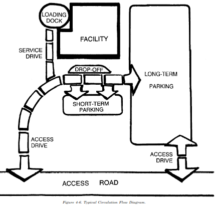
vehicles. Drives used only for service or emergency vehicles can be reduced substantially. Varying widths indicate the hierarchy of movement and reduce the amount of impermeable surface. The access drive should do the following:
(a) Take vehicles to their destination and return with minimum interference with or travel through parking areas, service areas or emergency zones.
(b) Enter and exit at the same point or on the same access road to discourage through traffic on site.
(c) Accommodate two-way traffic since oneway systems can create confusion and actually result in more vehicle movement.
(d) Promote separation of service drives from other drives.
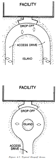
(3) Dropoff Areas. Drop-off areas should be provided for office, commercial, educational and community facilities with high use. This promotes both vehicular and pedestrian traffic flow. Figure 4-7 illustrates typical drop-off areas. Drop-off areas should be:
(a) Located at or near the front of the building and apart from entries into parking lots. Buses and shuttles require a separate drop-off area located away from the building entrance.
(b) Preferably on a one-way loop to avoid confusion.
(c) Sufficient in size to avoid vehicle conflicts and stoppages of traffic flow. Where a circular turn-around is used, the circle should be sized according to the design vehicle and provided with adequate radii.
(4) Parking.
(a) Parking should occur in lots or structures with a limited number of entrances and exits onto the access road or drive. Entrances and exits into different lots on the same site should be aligned or separated to provide adequate sight distance. One-way systems will be discouraged because they result in extended circulation through the lots when they are at or nearing capacity.
(b) Parking should be within convenient walking distance of a building entrance. Barrierfree parking should be located within 100’ of an accessible building entrance as required by “FED STD 795.” Parking for high turn-over or shortterm use (e.g., visitor, outpatient or delivery) should be located in a separate lot or signed and placed nearest the entrance. Usually, more distant parking areas should be maintained for employees.
(c) A minimum distance of 20’ should be maintained between parking and buildings. This provides adequate separation between the facility
and vehicular movement and adequate room for pedestrian movement.
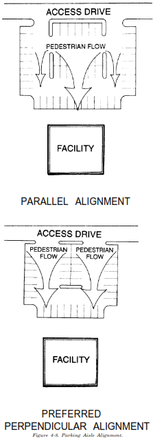
(d) Parking aisles should be aligned towards the building entrance to encourage more organized pedestrian flow. This alignment limits the number of places where pedestrian traffic must cross vehicular traffic. Barrier-free parking should not require movement across vehicular circulation paths. Figure 4-8 illustrates appropriate alignment.
(5) Emergency Vehicle Access. Direct access to a building will be provided for emergency vehicles. A separate access will be provided for ambulances. Fire truck access will be provided between buildings. This access may be provided on sidewalks or gravel paths designed for the vehicle. If a special drive is installed to accommodate emergency vehicles, it will provide sufficient room for the vehicle to turn and exit the site.
(6) Service Vehicles. Service vehicles can range in size from pickup trucks and vans to garbage and large delivery trucks. Service vehicles generally require larger turning radii, more room to maneuver, and holding space while deliveries or service occur. Service traffic should be separated as much as possible from the traffic flow on the access drive and in the traffic aisles of parking lots.
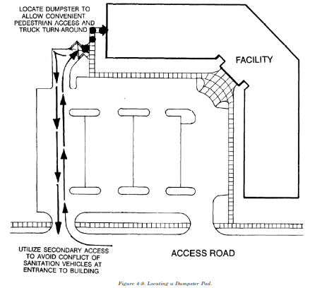
(a) Sanitation Vehicles. The circulation of sanitation vehicles is dictated by the locations of the dumpster pads. Pad locations should: provide convenient access for pedestrians taking garbage to the dumpster, provide convenient and easy access to vehicles emptying the dumpster, be in less visible areas of the site (e.g., the rear of buildings), and have sufficient room for screening with plant material, fences and/or walls. Sanitation vehicles should not have to turn around to exit the facility. When more than one dumpster location is required, it is desirable for sanitation vehicles to access each pad as part of a continuous loop. When the dumpster for a facility is located in the principal parking lot, the pad should be removed physically and visually from the building entrance and major pedestrian and vehicular circulation routes. Figure 4-9 illustrates how to locate a dumpster pad.
(b) Delivery Vehicles. Delivery zones should be placed in less visible areas of the site, at the rear or sides of buildings. Space requirements vary according to the type and size of vehicle and the need to access loading docks. Maneuvering room should be provided to allow trucks to back up and turn around to exit the site or to allow trucks to back up to the loading dock.
(7) Barrier-Free Accessibility. Barrier-free design will be in accordance with the requirements published in “FED STD 795.”
b. Pedestrian Circulation. Pedestrian circulation involves travel routes and areas of pedestrian concentration. TM 5-822-2 provides guidance on the geometric design of walks.
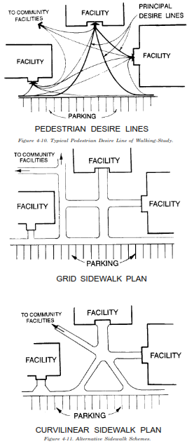
(1) Pedestrian Desire Lines. Pedestrian circulation should be based on pedestrians’ desired lines of walking between facilities. It is fairly simple to anticipate desire lines. People tend to follow the
most direct route when walking between two points. Desire lines should be weighted to predict the most travelled routes. This prevents crisscrossing the site with sidewalks. Figure 4-10 illustrates a typical desire line study. Because people often cut corners, more generous paved area should be provided at pathway intersections. Corners should be rounded or filleted. Where pedestrians can be expected to enter and exit a building or outdoor space from all directions, it is better to concentrate on the most direct and important routes, accepting that there will be some pedestrian flow across grassed areas. Adequate reception area should be provided at the doorway.
(2) Grid and Curvilinear Path Systems. A grid path system tends to provide the most direct access between locations. It is appropriate in areas with a strong sense of architectural definition. A more curvilinear path system can provide reasonably direct access while also providing more comfortable and interesting movement than a grid system. Figure 4-11 illustrates alternative sidewalk schemes. Topography and vegetation can be used to reinforce a sense of movement and direct sightlines. Topography and vegetation are less successful if used to block movement.
(3) Pedestrian Concentration. As the speed of pedestrian movement slows at the points of origin and destination, the space required to accommodate movement expands. Pedestrian movement is also interrupted so that people may meet, gather, wait or sit. In areas of pedestrian concentration (e.g., building entrances, drop-offs and small outdoor spaces between buildings), the space should be developed to accommodate these needs. General design techniques include the following:
(a) Widening walkways at the points of origin and destination.
(b) Providing adequate space for people to concentrate outside of the pedestrian traffic flow.
(c) Locating areas for people to sit on the dge or outside of the pedestrian flow.
(d) Providing both shaded and sunny areas for people to congregate or sit.
(4) Troop Formation Areas. Installations with training facilities require walkways for troops marching in formation between classrooms, barracks, dining halls and parade grounds. These walkways should be wide enough to accommodate personnel walking four abreast. They should be hard-surface.
4-4. Grading.
a. General. Existing and proposed topography on site can serve many purposes including the following:
(1) Emphasizing the prominence of facilities.
(2) Secluding and sheltering facilities.
(3) Helping to direct vehicular and pedestrian flows.
(4) Managing site runoff.
(5) Screening undesirable views or activities.
(6) Creating a more interesting natural character.
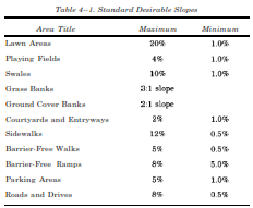
b. Standard Desirable Slopes. Grading should maintain existing topography while recognizing standard gradients for various functions and activities. Table 4-1 provides standard desirable slopes for various land uses.
c. Buildings.
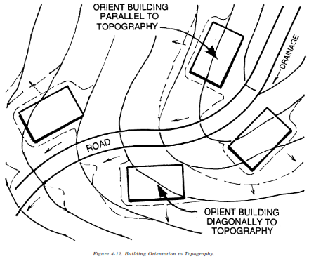
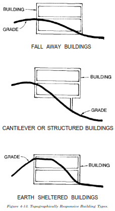
(1) Siting. Building orientation may be influenced by existing topography as well as the solar conditions determined in the solar study. Generally, the best orientation for buildings is parallel to slope. Buildings may also be located with their long axis perpendicular to grade. Even on moderate slopes, this usually requires some terracing as illustrated in figure 4-12. Slab-on-grade is the most economical and, therefore, predominant building type, especially on flat sites. To balance cut and fill, these structures are often sited diagonally to the slope. Figure 4-13 illustrates the following building types which respond to steeper topographic situations.
(a) Fall-away structures locate the front of the building at one elevation, lower the grade down the sides, and locate the back of the building at a lower elevation. Fall-away buildings can be used on grades ranging from 5 to 10%.
(b) Cantilevered buildings allow existing grade to remain substantially unaltered while the building is suspended in air, supported by a vertical structure installed into the substrate. Cantilevered buildings can be used on extremely steep slopes, up to about 18%.
(c) Earth-sheltered buildings use existing or created slopes or berms to insulate the structure.
(2) Floor Elevations. Finished or first floor elevations of buildings will be set a minimum six inches above adjacent outdoor grade. The finished floor elevation will be set to provide positive drainage around the entire perimeter of the building. The correct setting of this elevation is critical to a good grading plan. The building must not be placed too low in relation to the rest of the site. Where outdoor entrances (e.g., basement exits), occur below finished elevation, additional provisions, such as drain inlets, will be made to provide drainage.
Access and utility service should also be considered when setting the finished floor elevation.
(3) Outside Finished Grade. Outside finished grade should normally slope away from the building at a minimum five percent slope for approximately 10’. Where topography is too steep or space between buildings is too limited to maintain such a large area around the building, the slope of the outside finished grade can be increased. Additional drainage structures, such as yard inlets, will be provided.
d. Circulation. Grading for vehicular routes, pedestrian routes, and parking areas should respond to existing topography.
(1) Vehicular Circulation. Roads and drives should be laid out to traverse the topography as closely as possible to existing grade, within the standard grade limits. This reduces the amount of earthwork. Maximum grades are determined by the types of vehicles using the road and its design speed. Maximum grades are influenced by local weather conditions and practice. To the extent possible, the profile of a road or drive should
maintain a smooth grade line with gradual changes. Vertical curves should be sympathetic to and balance the severity of horizontal curves. On up or down slopes, particularly at intersections, sufficient flattening of the vertical curve should be provided to allow adequate sight distance and to avoid bumps at the crest or hidden dips. TM 5-822-2 provides additional guidance on the design of roads. Good grading for vehicular circulation should:
(a) Relate the roadway profile as closely as possible to existing topography.
(b) Allow adequate vertical and horizontal sight distances.
(c) Provide safe and smooth intersections.
(2) Parking Areas. A relatively constant grade should be maintained across parking areas. Slight changes in the slope interval should be made at intersections to provide a gradual transition into the main traffic flow. Changes may also be made at interior and exterior corners to direct or collect runoff. For areas laid out for 90-degree parking, 5% is the maximum desirable grade along the aisles and 1.5% for the transverse slope. For areas laid out for 60and 45-degree parking, 5% is the maximum desirable grade along the aisles with 1% for the transverse slope. Steeper grades create problems with opening and closing car doors and increase the potential of cars rolling.
(3) Sidewalks. Gradients for sidewalks can range from 0.5% to 15%. Gradients depend upon the quantity and types of pedestrians, the width of the pathway, and the surface. The normal minimum grade is 1 to 2%. Entrance areas or courtyards require a slightly steeper grade to ensure that runoff moves rapidly away from doors as well as locations where people sit or stand. Long, vertical climbs should be broken by short spans. The spans should continue upward movement at a gentler grade to reduce exertion. Ramps and steps can access steeper topography (where grades are greater than 5%) and minimize regrading. TM 5-822-2 provides additional guidance on grading walks. Grades are critical to barrier-free accessibility. Careful thought is needed to make all facilities, not just buildings, accessible. “FED STD
795” provides guidance on accessibility requirements. Sensitive site grading minimizes the need for architectural ramping into buildings. Such ramping creates additional costs and a less aesthetic appearance.
e. Balance of Cut and Fill. Site design should balance the quantity of cut and fill. Balancing cut and fill creates a more pleasing transition of the regraded areas into the natural site. It minimizes the costs of hauling in additional fill or removing and disposing of extra cut. Figure 4-14 illustrates balancing cut and fill.
f. Transition. Figure 4-15 illustrates how grading should be designed to accommodate proposed facilities and to effect a smooth transition from the regarded area to the existing topography. When berms or mounds are introduced into the landscape, they should give the appearan