Chapter 6
Design for On-Site Vehicular Circulation and Parking
6-1. General.
This chapter provides general guidelines and criteria, or standards, for determining the size, layout, and design of on-site vehicular circulation and parking. The chapter covers access and service drives; parking areas; and special vehicle-use areas including gateways, drop-offs, dumpsters, deliveries, and drive-in facilities. This chapter also addresses methods for mitigating the visual impact of parking and other vehicle use areas. MTMC provides detailed information on all aspects of circulation design.
6-2. Design Vehicles.
A variety of vehicles can be expected on any site. These include cars, pick-up trucks, garbage trucks, delivery vans and trucks, buses, recreation vehicles, fire trucks, oversized or tracked organizational vehicles, and motorcycles. Site entrances and exits should be designed to accommodate the largest vehicle using the site. Other areas (e.g, parking lots or loading docks which have special requirements) should be designed for the largest vehicle using the area.
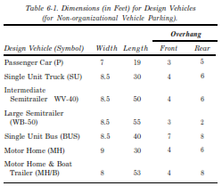
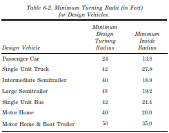
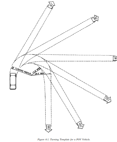
a. Vehicle Dimensions and Turning Radii. In A Policy on Geometric Design of Highways and Streets, the American Association of State Highway and Transportation Officials (AASHTO) places vehicles into three general classes: passenger cars, trucks, and buses/recreation vehicles. The passenger car class includes light delivery trucks such as vans and pick-ups. Table 6-1 lists dimensions for some of the more commonly found vehicles. Table 6-2 lists minimum turning radii for the same vehicles. AASHTO provides an expanded list with additional dimensions and information. For the purposes of design, the design vehicles have larger physical dimensions and larger minimum turning radii than almost all vehicles in their classes.
b. POV Vehicles. The AASHTO passenger car is equivalent to a non-organizational or POV vehicle. Figure 6-1 illustrates a turning template showing the turning paths and radii of a POV vehicle. AASHTO provides turning templates for the other design vehicles.
6-3. Access and Service Drives.
Access drives carry all vehicular traffic on site. They should be designed to accommodate the full range of vehicles. Service drives are limited to special vehicle traffic. They should be designed to accommodate the particular vehicle.
a. Spacing. Location of access drives should follow these spacing guidelines:
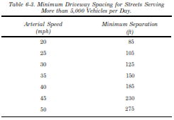
(1) Maintain 200’ or more between access drives on arterial roads. Table 6-3 provides acceptable minimum spacing if this is not possible.
(2) Maintain a minimum spacing of 1,200 to 1,500’ between a signalized drive and adjacent signalized intersection. If the signalized drive is a T-intersection, 600’ is an acceptable minimum spacing.
(3) Coordinate drive signals within 2,500’ of adjacent signals.
(4) Maintain a minimum spacing of 35 to 50’ on low-volume (5,000 vehicles per day), low-speed (30 mph) roads.
b. Corner Clearances. Access drives near major intersections adversely affect traffic operations. They may result in unexpected conflicts with vehicles turning at the intersection. A minimum clearance of 50’ should be maintained between access drives and major intersections. MTMC provides further guidance on recommended corner clearances.
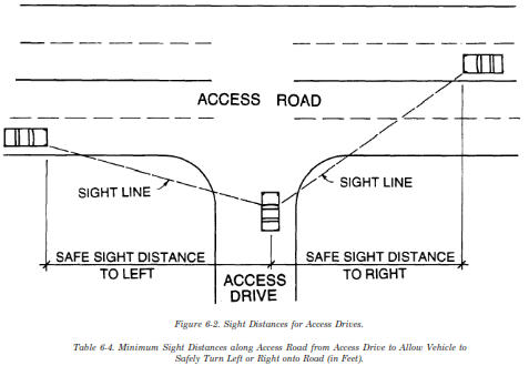
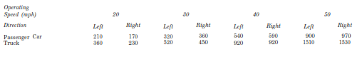
c. Sight Distances. Adequate sight distance should be provided for vehicles entering and exiting the access drive. Figure 6-2 illustrates safe sight distances as determined by table 6-4. If sight distance is not adequate, the following alternatives should be considered:
(1) Removal of sight obstructions.
(2) Relocation of the access drive to a more favorable location along the access road.
(3) Prohibition of critical movements at the access drive.
(4) Relocation of the access drive to another access road.
d. Left turns. Access should limit conflict on the through road by preventing certain maneuvers (e.g., left turns.) Left turns should be prohibited under the following conditions:
(1) Inadequate corner clearance.
(2) Inadequate sight distance.
(3) Inadequate driveway spacing.
(4) Median opening too close to another median opening.
NOTE: Sight distances are based on the following assumptions:
1. Upon turning left or right when exiting the access drive, the vehicle accelerates to the operating speed of the access road without causing approaching vehicles to reduce speed by more than 10 mph.
2. Upon turning left when entering the access drive, the vehicle clears the near half of the access road without causing approaching vehicles to reduce speed by more than 10 mph.
3. Turns are 90-degree.
4. The access road and the access drive are on level terrain.
e. Entrances. Entrances to and from access drives should have:
(1) Minimum turning radii for the largest vehicle expected to use the site.
(2) A minimum 10’-wide traffic island where entry and exit lanes into the site are separated.
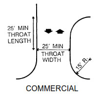
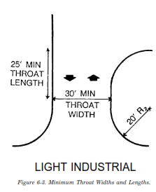
(3) Minimum throat widths and lengths to accommodate incoming and outgoing traffic. Figure 6-3 illustrates throat dimensions.
(4) Sufficient width to accommodate singleor double-lane traffic depending upon the design vehicle using the route.
(5) A minimum 100’ unobstructed sight distance for turns from parking lots and service drives onto the access drive.
f. Grading and Drainage. Grading for access drives should respond to the natural topography. Grading should observe commonly accepted minimum and maximum gradients for the locale. TM 5-822-2 provides additional information on the grading of drives.
g. Pavement. TM 5-822-5 provides guidance for the design and engineering of roadway pavements.
h. Traffic Controls. TM 5-822-2 and the Manual on Uniform Traffic Control Devices for Streets and Highways (ANSI D 6.1e) provide information on devices to control and direct traffic.
i. Lighting. TM 5-811-1 provides guidance on roadway lighting.
6-4. POV Parking Areas.
POV parking includes on-street parking, off-street parking lots and parking structures.
a. On-street Parking. On-street parking will be limited to parallel parking spaces. There should be sufficient length and width to allow comfortable movement into and out of the space. There should be sufficient width to adequately separate the parked car from traffic.
b. Off-street Parking Lots. Off-street parking lots are the principal means of parking on installations.
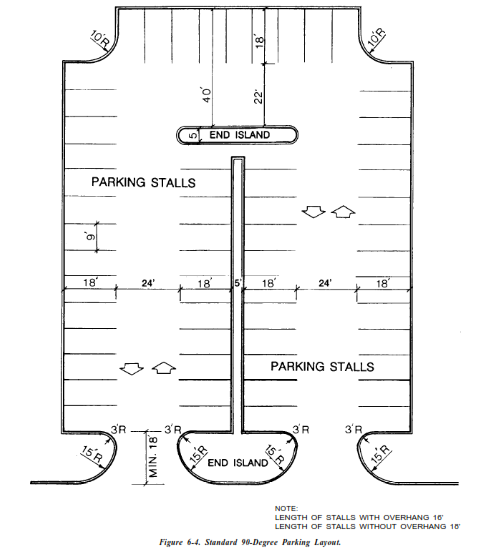
(1) Layout. A 90-degree parking layout is preferable. Where a fast rate of turnover is expected or where required by site limitations, a 60or 45degree layout with one-way aisles may be used. Figure 6-4 illustrates a standard 90-degree parking lot layout. Parking lot layout should:
(a) Maintain two-way movement if at all possible.
(b) Avoid dead end parking lots in all situations.
(c) Provide more than one entrance and exit in parking lots with more than 100 parking spaces.
(d) Provide traffic breaks in parking aisles longer than 350’.
(e) Use compact parking spaces only if recommended by a traffic impact study.
(f) Provide curbing or a painted line at the ends of stalls to control placement of vehicles.
(g) Provide adequate walkway width to allow comfortable pedestrian movement in areas of bumper overhang.
(h) Provide curb cuts for barrier-free access to sidewalks.
(i) Consider snow removal.
(2) Islands and Medians. Islands should be located at the ends and intersections of parking aisles. They establish turning radii for vehicular movement and protect end stalls. Turning radii should be based on the design vehicle. Turning radii should be sufficient to allow traffic movement without destroying the island and/or curbing. Figure 6-5 illustrates criteria for laying out islands and medians. Landscaped islands and/or medians should be placed in the midst of parking lots to:
(a) Separate different vehicles and user types.
(b) Break up the expanse of impermeable and unshaded surface.
(c) Provide a more pleasing visual appearance.
(d) Preserve existing vegetation.
(e) Consider snow removal.
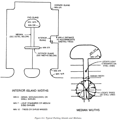
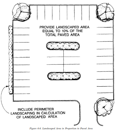
(3) Landscaping. The landscaped area within and around a parking lot is usually based on a proportional amount of “green” space to paved area. A common minimum standard is 10% of the paved area, including planted islands, medians and perimeter areas. Figure 6-6 illustrates the areas used to attain this proportion. As a general rule, the landscaped area should be increased from the minimum standard in parking lots associated with residential land use. The standard may be decreased for commercial and industrial land uses. There should be adequate room within islands and medians to accommodate plant material and light poles. Where medians are narrow, tree trunks and light standards should be located on the stall lines between parking spaces.
(4) Pedestrian Use. Islands and medians can be partially or completely paved to service pedestrian traffic. Pedestrians tend to use parking aisles, especially if medians are not generous and do not allow for comfortable movement between vehicles. Should the median be designed as a sidewalk, it should be sufficiently wide (a minimum eight feet) to allow for pedestrian movement and bumper overhang.
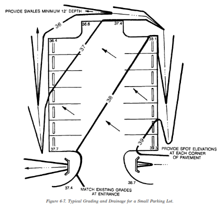
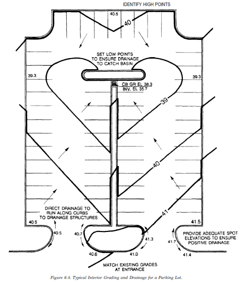
(5) Grading and Drainage. Figures 6-7 and 6-8 illustrate basic principles for grading and draining parking lots. Parking lot design should:
(a) Maintain a relatively constant grade across the lot while providing enough slope and adequate spot elevations to properly direct drainage off the lot or to drainage inlets.
(b) Use islands and medians to accommodate topographic change between the access drive and parking areas or between different parking levels.
(c) ‘Sheet drainage across small, flat parking lots into swales in surrounding grassed areas.
(d) Control runoff with curbing and direct it to the sides and corners of larger (more than 100 spaces) and/or steeper lots.
(e) Avoid channelling of sheet flow.
(f) Avoid ponding water.
(g) Avoid creation of an impoundment zone in the center of the lot.
(h) Never trap water in corners.
(i) Provide sufficient spot elevations to move water off the lot.
(j) Provide adequate drainage inlets to move water off the lot.
(6) Lighting. Parking lots should be illuminated for traffic safety and security. Uniform coverage should be provided across the lot. TM 5-811-1 provides guidance on lighting parking areas.
(7) Pavement Marking and Signage. The Manual on Uniform Traffic Control Devices for Streets and Highways (ANSI D 6.1e) provides guidance on pavement marking and signage.
c. Parking Structures. Parking structures may be separate buildings or built underground in conjunction with other building development. For
underground structures providing a transition between the access road or drive which permits enough vertical height at the structure’s entrance is critical to successfully incorporating the structure into the site. If the roof of the structure is to be used as a site amenity or is to incorporate recreational activity, the site designer should coordinate with the structural engineer to ensure that the roof can support the weight of such additional elements as plant material and soil. The book Parking provides guidance on development of parking structures.
6-5. Parking Areas for Petroleum, Oil and lubricates (POL) Vehicles.
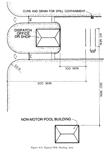
Figure 6-9 illustrates a typical POL parking area. POL parking area design should:
a. Provide traffic flow which allows vehicles to enter the parking stall with a single turn and to exit in a continuous straightforward movement.
b. Locate stalls a minimum 100’ away from
motor pool shops and dispatch offices.
c. Locate stalls a minimum 300’ away from non-motor pool buildings, public highways and public gathering areas.
d. Maintain a minimum 10’ distance between vehicles.
e. Maintain a minimum 1% and maximum 5% gradient.
f. Provide adequate positive drainage and adequate spill containment to prevent contamination of normal storm drainage running off site.
6-6. Special Circulation Areas.
Circulation areas for other than normal automobile traffic have special requirements to make them function successfully. They require additional space to accommodate unusual traffic patterns and to provide more room, especially larger turning radii, for manueverability.
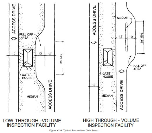
a. Gateways. Figure 6-10 illustrates typical lowvolume gate areas. Design for gateways should be discussed with the Provost Marshal and coordinated with the site’s physical security requirements. Design for gate areas should:
(1) Provide adequate width for a gatehouse, traffic island, travel lane and, if necessary, pullover lane for questioning or search.
(2) Provide enough straight length on the access drive to accommodate stacking for waiting vehicles and to allow an adequate transition zone into and out of the major traffic flow.
(3) Use curb around the traffic island to create better visibility and prevent poor drainage at the gatehouse.
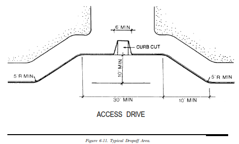
b. Dropoff Areas. Figure 6-11 illustrates a typical drop-off area. Design of drop-off areas should:
(1) Provide adequate width and length to accommodate the movement of cars in and out of the flow of traffic.
(2) Provide enough width and length for vehicles to move entirely out of the traffic flow where cars and buses are using the same drop-off zone.
(3) Maintain a fairly level grade across the area.
(4) Have curb cuts for barrier-free access onto sidewalks.
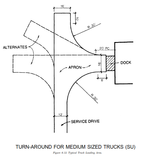
c. Delivery and Service Zones. Delivery and service trucks can access rear or side doors in buildings. These services should not cross pedestrian traffic or take place over sidewalks. Delivery may require dock facilities which need sufficient room to accommodate the necessary maneuvering into and out of the dock. Figure 6-12 illustrates a typical truck loading area for a single-unit truck. Design for delivery zones should:
(1) On a continuous-flow vehicular system, provide enough length to pull forward, then back into the dock, and then move forward again to exit.
(2) On a dead-end service drive, provide enough space for the necessary turning movements.
(3) Provide positive drainage away from the loading dock. This may be accommodated by a
six-inch drop across the first 20’ away from the loading dock to a drainage inlet.
(4) Maintain as level a grade as possible so that trucks do not have to move uphill to the dock. The maximum standard desirable grade is 3%.
(5) Be screened with walls, fences, plant material or a combination of these.
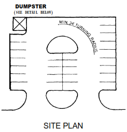
d. Dumpsters. The design of trash removal areas is controlled by the size and location of the dumpster pad. Figure 6-13 illustrates a typical dumpster pad layout. Design for dumpster pads should:
(1) Allow sanitation trucks to approach the pad in a straightforward manner, align with the dumpster, reverse away from the pad and exit the site. It is preferable if trucks do not have to reverse out of the site or turn to exit the site but can maintain a continuous forward movement.
(2) Locate dumpsters on concrete pads.
(3) Provide positive drainage away from the pad.
(4) Screen the pad with fences, walls, plant material or a combination of these.
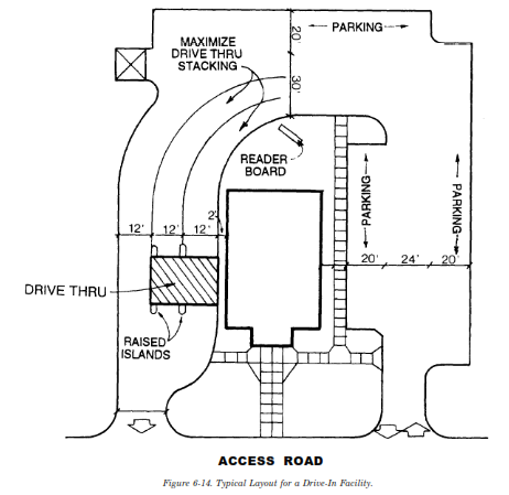
e. Drive-in Facilities. Drive-in facilities, such as banks and fast-food restaurants, require careful and clear establishment of traffic patterns and a continuous traffic flow. The standard configuration for a singleor double-service position facility does not lend itself to a two-lane approach and departure design. It usually relies on some form of loop system. Figure 6-14 illustrates a typical layout for a drive-in facility. Design for drive-in facilities should:
(1) Maintain traffic flow into and out of the drive-in windows while working with other on-site vehicular traffic flow including parking.
(2) Minimize interference with pedestrian traffic flow.
(3) Provide adequate stacking room in the drive-through lanes for waiting vehicles.
(4) Provide adequate stacking room on-site to prevent spillage out into access roads.
(5) Use curb and planting islands to control traffic movement.
(6) Use signs and directional arrows on the pavement to help avoid confusion.
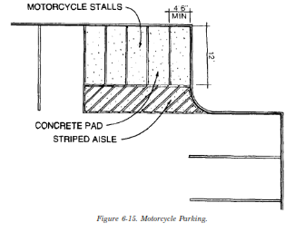
f. Motorcycle Parking. Figure 6-15 illustrates a typical motorcycle parking area. Design for motorcycle parking should:
(1) Locate parking close to building entrances.
(2) Locate parking in parking lot corners.
(3) Locate parking away from low areas which catch drainage.
(4) Place parking on a concrete pad which is resistant to kick stands in warm weather.
(5) Provide adequate signage and pavement striping.
6-7. Mitigating Vehicular Impact.
Because circulation and parking consume such large areas, all possible methods of mitigating their impact on site should be explored. A minimum 20’ wide buffer strip should separate all parking areas from neighboring streets.
a. Grading. Working closely with existing topography in the placement of parking areas limits cut and fill and creates a more pleasant flow experience. Locating parking on flatter slopes also limits cut and fill. Where slopes are steeper, more than one level of parking may be used to break up the parking expanse. Locating parking structures partially underground or surrounding them with earth banks lessens their visual impact. In order to avoid the visual and lighting impact of automobiles, parking should not be placed at an elevation above the finished floor elevation of surrounding buildings.
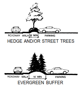
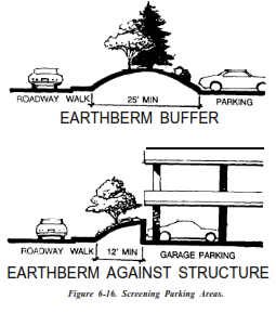
b. Screening. Locating parking below the grade of neighboring streets and surrounding land uses helps mitigate its visual impact. Berms and plant material alone or in combination should be used to screen parking lots from neighboring roads and surrounding land use. Architectural screens such as walls or fences may also be used. The design of parking screens should relate to the natural or architectural character of the site as a whole. Earth berms should be designed relative to the 52” viewing height, or eye level, of a motorist. Figure 6-16 illustrates various methods of screen-ing parking areas. It may be impractical to provide continuous screens around large parking areas. Judicious placement of berms and plant material can still break up the uninterrupted line of vehicles and significantly lessen their impact. Landscape treatment of islands and medians can also be used to break up large expanses of parking.