Chapter 5
Site Design
5-1. General.
Site design:
a. Locates primary and support facilities on site and addresses both positive and negative site concerns which will impact development through the preparation of the sketch site plan.
b. Details facilities on site and develops specific methods for dealing with site concerns through the concept site plan.
5-2. Concept Development.
Site design begins by continuing concept development through the preparation of sketch site plans and concept site plans. In each step, alternatives may be explored and evaluated to arrive at the optimal design. The site design guidelines discussed in chapter 4 should form the basis of the evaluation. The level of detail which is prepared for each step will depend on the size and complexity of the project, but the general procedures listed below should be followed for every design.
5-3. Sketch Site Plan.
The sketch plan refines the preferred spatial relationships diagram. The sketch site plan shows the initial design of the facilities and site at scale. It begins to address the site in detail. Buildings, roads, parking areas, and other structural elements assume form and definition in relation to the site elements. The sketch site plan is still geographically loose, usually free-hand, but is drawn to scale.
a. Principal Considerations. The sketch site plan should address the following principal considerations:
(1) Buildings. The plan should:
(a) Define recognizable shapes for facilities.
(b) Clearly identify extrances.
(c) Establish a building orientation which addresses energy conservation needs (based on a solar study), access to other facilities, and visibility.
(d) Mass buildings to define outdoor space when there is more than one building or a new building is introduced into an area with other existing structures.
(2) Vehicular Circulation and Parking. The plan should:
(a) Provide the general location of the access drive.
(b) Provide the location of drives for emergency and service vehicles.
(c) Locate required gates or vehicle search areas.
(d) Separate vehicular circulation and parking.
(e) Locate parking areas and orient them towards facilities.
(f) Locate drop-off areas and/or waiting areas for buses.
(3) Pedestrian Circulation. The plan should:
(a) Establish pedestrian paths along anticipated desire lines.
(b) Identify expected areas of pedestrian concentration.
(c) Suggest methods of handling these areas, from widening of paths to development of courtyards.
(4) Grading and Drainage. The plan should:
(a) Set the initial finished floor elevations for all buildings.
(b) Identify means other than grading necessary to maintain positive drainage around the building(s).
(c) Determine approximate grades for the drives and parking areas.
(d) Identify critical elevations (e.g., low points which could produce ponding or elevations on existing trees which are to be saved.)
(e) Review existing storm drainage, including areas of sheet flow and swales, to determine if it can be maintained.
(f) Suggest methods for handling drainage if the site cannot accommodate the increased runoff.
(g) Delineate areas requiring erosion control.
(5) Energy Conservation. The plan should:
(a) Note climatic conditions which can be improved or enhanced.
(b) Identify potential locations for windbreaks, shade walls, etc.
(6) Utilities. The plan should:
(a) Identify access points and connecting routes to existing utilities.
(b) Establish requirements for upgrading existing systems.
(7) Physical Security. The plan should:
(a) Locate special physical security requirements (e.g., search areas and the serpentine layout of access drives.)
(b) Roughly locate additional measures (e.g., walls or fences.)
(8) Planting. The plan should:
(a) Locate vegetative massing and identify its proposed functions.
(b) Locate existing plant material to be preserved.
(9) Outdoor Space. The plan should:
(a) Begin to provide scale and definition for outdoor spaces.
(b) Indicate the functions outdoor space will accommodate (e.g., formation grounds, travel zones, or active and passive recreation.)
(c) Size and locate facilities for active recreation (e.g., tennis or basketball courts.)
(10) Site Amenities. The plan should identify any critical areas which need special design consideration (e.g., site entries, courtyards or picnic areas.)
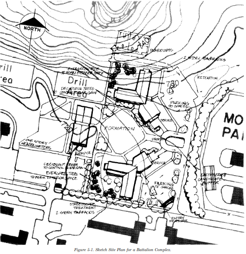
b. Sketch Site Plan for a Battalion Complex. Figure 5-1 illustrates a sketch site plan for a battalion complex. It shows the initial design of the preferred alternative described in chapter 4. It addresses the concerns which were judged significant to the project in that alternative. The plan locates the buildings in an arrangement which, together with the primary vehicular and pedestrian circulation, focuses on the large open space of the formation grounds. A smaller, more enclosed private space is developed in the ell of each of the barracks units. This helps create a desirable residential character within the complex. The barracks’ access drive and turnaround create a formal entrance into the complex. By focusing on the formation grounds, the turnaround visually and physically presents the complex. The barracks’ access drive and turnaround allows service vehicles to enter and exit the site without moving through the parking areas. Service for the battalion headquarters building is maintained on the perimeter of its parking area. Service vehicles will not have to travel through parking aisles. Pedestrian circulation within the complex provides easy access to and from parking areas and to the game courts. There is convenient movement between the various buildings. Instead of crossing the formation grounds, the sidewalk system is used to define the area. Grading on site is designed to direct the principal drainage flow from the barracks and their parking lots toward the existing drainage culvert. The parking area behind the battalion headquarters is drained towards the existing storm system located along the access road. An extensive vegetative screen is developed between the complex and the motor pool area. Game courts are located just north of the complex where they can conveniently serve future expansion needs. At the intersection of the access road and barracks’ access drive, an area is designated for a sign and landscaping to identify the complex. The landscaping will also serve to screen the parking area behind it.
5-4. Concept Site Plan.
The concept site plan further refines and details the sketch site plan. The concept site plan is a hardline plan, at scale. It provides accurate locations, dimensions and elevations for facilities and site improvements. The level of detail achieved depends upon the level of detail supplied concerning the architecture, utilities and other elements affecting the site. The concept plan cannot resolve all potential problems, but it does attempt to recognize them. The sooner consideration is given to all factors affecting site development, the better. The concept site plan can help make design team members aware of the impacts of the individual designs before those designs become too entrenched and difficult to change. The concept site plan provides sufficient detail to serve as the basis for construction documents for the project. The concept site plan does not resolve all site problems but indicates, at a minimum, how they will be addressed and their cost implications.
a. Principal Considerations. The concept site plan should address the following principal considerations:
(1) Construction Lines. The plan should
(a) Locate critical construction lines (e.g., setbacks, easements or building spacing.)
(b) Ensure that facilities do not encroach upon any of these boundaries or zones.
(2) Buildings. The plan should:
(a) More precisely define the location of the building footprint.
(b) Identify all entrances, including fire exits.
(c) Further refine the outdoor space between Facilities.
(3) Vehicular Circulation and Parking. The plan should:
(a) Provide further definition of access, service and emergency drives.
(b) Provide further definition of parking areas.
(c) Indicate appropriate turning radii to be used throughout the site.
(d) Delineate parking spaces, including barrier-free spaces, to assure the proper count.
(e) Define parking islands and medians.
(f) Further refine gate and drop-off areas to ensure that they function properly.
(g) Ensure that sufficient turn-around room is provided for service and emergency vehicle routes.
(h) Locate dumpster pads.
(4) Pedestrian Circulation. The plan should:
(a) Further refine pedestrian circulation to assure clear and convenient flow of pedestrian movement.
(b) Assure barrier-free accessibility between buildings and from barrier-free parking spaces to at least one building entrance.
(c) Note the location of any necessary ramps.
(d) Identify means of using topography and plant material to help direct pedestrian flow.
(5) Grading and Drainage. The plan should:
(a) Establish an overall grading concept for the site, showing proposed contours and critical elevations on roadways, in parking lots, on walkways and at building entrances.
(b) Define and locate stormwater management areas on site.
(c) Determine if curb or curb and gutter will be used to control stormwater.
(d) Locate and indicate critical elevations for other drainage facilities such as swales, paved ditches, yard drains and underground systems.
(e) Determine the need for retention or detention ponds and locate them if they are necessary.
(f) Locate and provide critical elevations for structures such as retaining walls or steps which are needed to facilitate grading conditions.
(g) Indicate methods for dealing with erosion or sediment control problems.
(6) Energy Conservation. The plan should further delineate means for dealing with climatic conditions.
(7) Utilities. The plan should:
(a) Further define the locations of utility lines.
(b) Further identify access points from the supply lines and entry points into buildings.
(c) Ensure that utility lines are not located under proposed paved areas.
(d) Ensure that utility lines are located logically for future expansion.
(8) Lighting. The plan should:
(a) Develop an initial lighting coverage scheme.
(b) Identify areas requiring higher lighting levels or special lighting.
(9) Physical Security. The plan should further refine proposed security measures.
(10) Landscape Plantings. The plan should:
(a) Further refine the planting scheme by broadly describing the types of vegetative massing (e.g., large deciduous trees, flowering trees, evergreen trees, shrub beds, etc.).
(b) Identify lawn areas.
(11) Outdoor Spaces and Site Amenities. The plan should:
(a) Further reline the design for outdoor areas.
(b) Give preliminary consideration to the location of site features (e.g., lighting, signs, fountains and site furniture.)
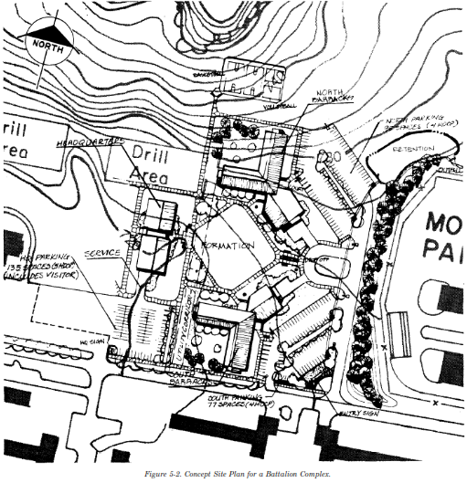
b. Concept Site Plan for a Battalion Complex.
Figure 5-2 illustrates a concept site plan for a battalion complex. This plan further refines and details the sketch site plan. A more formal entry has been suggested for both the drop-off area and the battalion headquarters building. The parking areas are more fully articulated and include handicapped spaces. Landscaped medians have been added to break up the expanse of pavement. Pedestrian circulation eliminates the sidewalks which previously ran along the parking lots and concentrates pick-up of pedestrian movement at the turnaround. Finished floor elevations have been set for the buildings. The grading concept allows barrier-free accessibility across the site. Grading will drain the barracks’ parking lots into inlets which can be piped to the existing culvert. An initial scheme for lighting coverage has also been developed. The planting scheme has been further refined to: develop the sidewalk islands; substantially screen the barracks’ service areas; contribute to the aesthetic quality of the open area around the formation grounds; and reduce solar gain on the south sides of the barracks’ buildings.
5-5. Confined Sites.
Confined sites are located in areas which are already densely developed. They present critical situations on many installations. Confined sites create interface difficulties with the surrounding area. Their constricted sizes and the more complex surrounding conditions (e.g., existing structures, circulation and utilities) place physical and cost limitations on their development. Confined sites should be approached with the same planning and design process as any other site. Confined sites raise site planning issues because candidate sites may not be appropriate to the development for which they have been selected. Site analysis should determine the suitability of confined sites and document the reasons for and against project development. Confined sites present site design problems which may require more flexibility and creativity in the solutions. The planning and design challenges associated with development of confined sites are discussed below. The description of an Information Systems Facility project addresses some of the common issues found on confined sites.
a. Site Analysis. Because of their locations, confined sites tend to be more greatly impacted by off-site and man-made conditions. They demand thorough and sensitive site analysis since the sites are greatly constricted from the beginning. Problems related to confined sites include the following:
(1) Inadequate size-not necessarily for the primary facility, but for support facilities.
(2) No room for future expansion.
(3) Location in the midst of incompatible land uses which might be negatively impacted by a proposed facility.
(4) Inadequate access for proposed vehicular circulation.
(5) Creation of traffic problems (e.g., congestion or accident incidence) by increasing trips to and from the site on inadequate access roads.
(6) Encroachment upon or obliteration of previous uses for adjacent facilities (e.g., parking.)
(7) Expensive relocation or difficult siting of existing utilities.
b. Concept Development. Concept development uses the same procedures, or courses of action, no matter how small or large, simple or complex a project is. The same steps need to be taken and the fundamental issues addressed. A confined site is usually small and constricted. It may have room for the addition of only one building. On the surface, this may appear to be a simpler problem with a single solution. However, there are still many variables on site (e.g., circulation, grading, utilities, etc.). These variables need to be addressed in the same methodical manner as for larger and more complex sites. On confined sites, there is literally less room for error. It can be more difficult to control problems (e.g., drainage or parking) on the site and prevent them from spilling over into the surrounding area. Some of the most common challenges on confined sites are:
(1) Maintaining setbacks and responding creatively to space constraints.
(2) Relating new facilities to existing facilities visually and physically.
(3) Providing access and parking.
(4) Managing stormwater runoff.
(5) Providing new utilities and avoiding relocation of existing utilities.
(6) Conserving the natural environment.
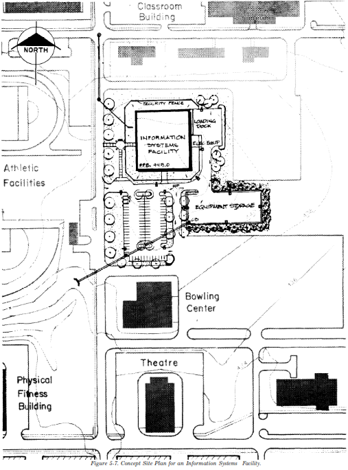
c. Planning and Design for an Information Systems Facility on a Confined Site. An information systems facility consists of one large building with associated equipment storage, service and parking areas. The facility requires a security fence and substantial screening of the equipment storage and loading dock areas.
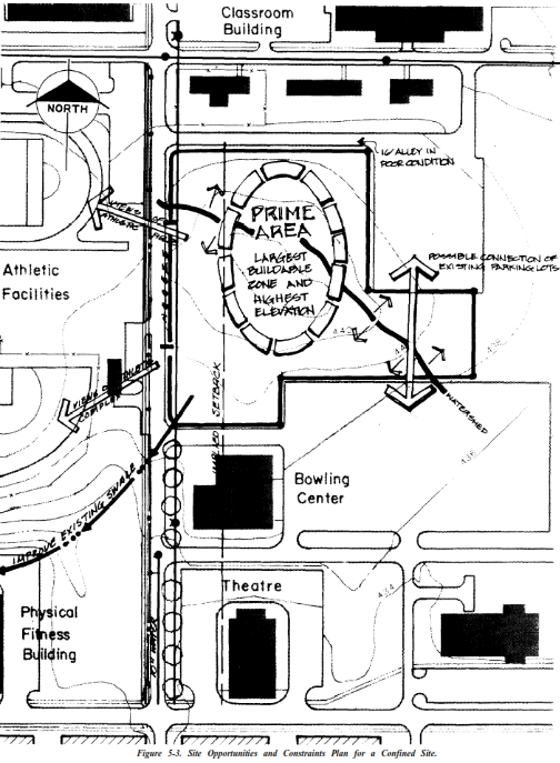
(1) Site Analysis. Figure 5-3 illustrates a site opportunities and constraints plan for an Information Systems Facility. The candidate site is a confined site and presents some of the typical problems including the following:
(a) Irregular site configuration closely confined by surrounding facilities.
(b) Setbacks defined by existing buildings.
(c) High visibility to surrounding facilities.
(d) Potential for traffic problems and confusion at entrances to the access road.
(e) Limited area for managing drainage on site.
(2) Spatial Relationships Diagrams.
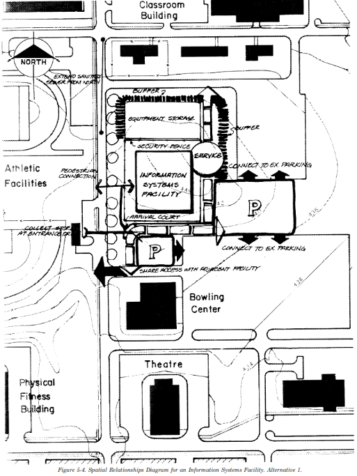
(a) Alternative I. Figure 5-4 shows the building in the prime development area identified on the site opportunities and constraints plan. The diagram simplifies vehicular circulation by sharing access with the existing bowling center. It locates the proposed parking area between the two existing lots to take advantage of existing entrances and exits. Another small parking lot is provided between the facility and the bowling center. A drop-off area is provided. Movement of service vehicles in and out of the site is accomplished on the through access drive. This decreases the space required for the loading dock. Placing the equipment storage to the side of the facility provides additional security. However, it locates an unattractive area of the facility next to the surrounding buildings.
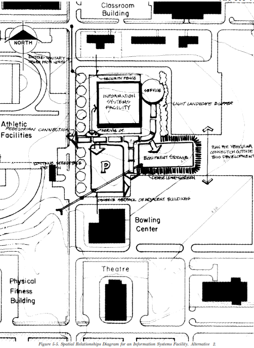
(b) Alternative 2. Figure 5-5 also shows the building in the prime development area. However, the building location establishes a better visual relationship with surrounding buildings and the access road. The site has its own entrance. This avoids confusion with the traffic into the bowling center and provides a more convenient drop-off. Service vehicle movement is direct and entirely separated from the bowling center traffic. Parking is concentrated in one lot which does feed off the existing circulation established by the bowling center. The equipment storage is placed between the two existing lots. It is still heavily screened. This location avoids the massive expanse of parking shown in alternative I. It places the storage in a more remote and easily screened section of the site, away from surrounding buildings.
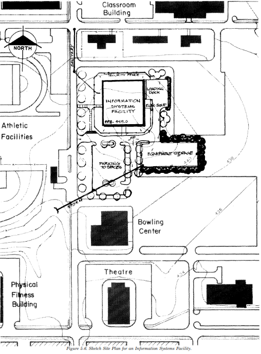
(3) Sketch Site Plan. Figure 5-6 illustrates the initial design for alternative 2 which was judged to be the better alternative. The sketch site plan not only locates the building but also determines its relationship to the surrounding buildings. The plan places the vehicular circulation and parking to ensure that they will fit comfortably and meet the requirements for size and maneuverability. The plan articulates the limited pedestrian circulation and provides for pedestrian flow across the street to the athletic facilities. The plan locates the security fence. It also locates the planting necessary to screen both the equipment storage and loading dock. Grading for the site is minimal but must provide sufficient slope to carry drainage to the existing culvert across the access road. The plan identifies initial routes and access points to existing utilities.
(4) Concept Site Plan. Figure 5-7 further refines the sketch site plan. It ensures that all setback and spacing requirements around the building have been met. The plan suggests establishment of street trees along the access road and continuing this landscape treatment around the parking area to mitigate its impact. It sets the finished floor elevation for the building necessary to accommodate access to existing utility systems. It also establishes the location of the high point on the access drive necessary to ensure positive drainage on the site. The locations of inlets have been established so that storm water can be piped off site to the existing culvert. An initial scheme for lighting coverage on site has also been developed.