Figure D-3. Labeling sector of fire.
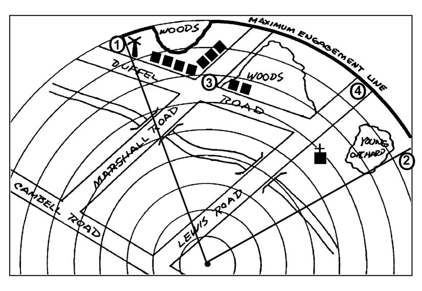
Figure D-4. Placement of maximum engagement line.
D-4
FM 3-22.34
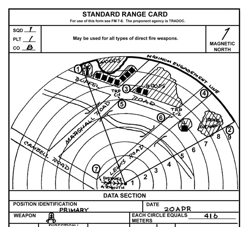
d. Number the anticipated target engagement areas (ATEAs) from left to right, starting with number 3. Place a number at the maximum engagement range of the target on the range card and circle the number (Figure D-5, page D-6).
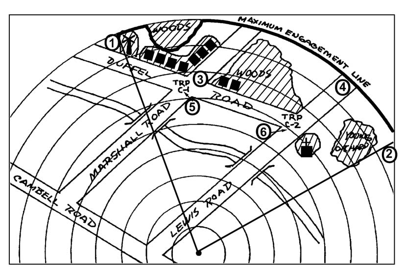
e. Number the TRPs from left to right. Place the number below or next to the TRP
on the range card and circle the number (Figure D-6, page D-6).
f. Place diagonal lines, or the words “dead space,” where dead space occurs (Figure D-7, page D-7).
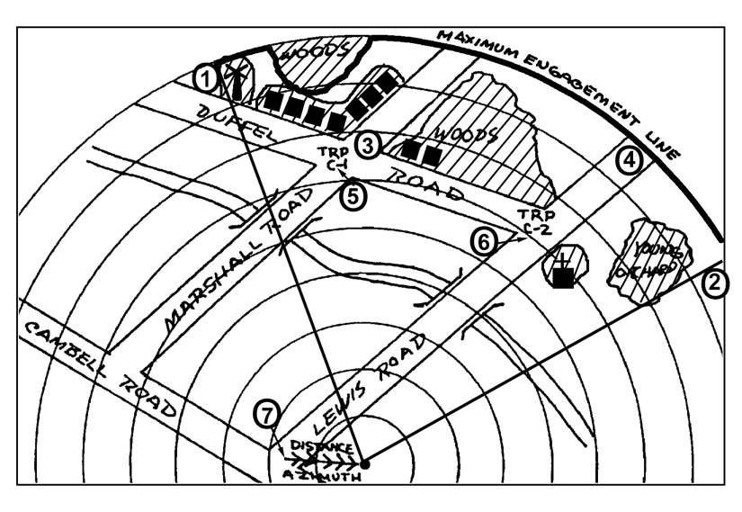
g. Use a compass to determine the azimuth from the firing position to the known point. Convert the direction to a back azimuth. Draw a line with multiple arrows from the known point to the firing position. Place a number at the known point and circle the number (Figure D-8, page D-7).
h. Fill in the marginal information at the top of the card.
(1)
Unit Description− SQD, PLT, CO. Never indicate a unit higher than company level.
(2)
Magnetic North. Orient the range card with the terrain. Place the compass on the range card. Determine the direction of magnetic north arrow and mark it on the card.
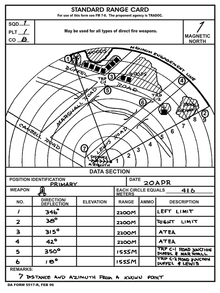
i. Fill in the data section at the bottom of the card.
(1)
Position Identification. List either primary, alternate, or supplementary.
(2)
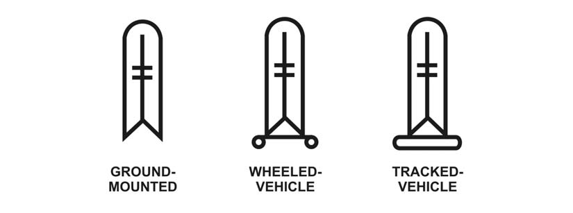
Weapon. See Figure D-9 (page D-8) for weapon symbols.
(3)
Date. List the day and month.
(4)
Each circle equals ______ meters. Write the distance between the circles in meters. To determine the distance, count the intervals from the weapon to the maximum engagement line (as determined by the squad leader). Divide the amount of intervals into the range of the maximum engagement line. This will give the distance between circles (Figure D-10, page D-8).
Example: 9 intervals into 3,750 meters = 416 meters between circles.
(5)
No. (Number). Starting with number 1, list the left limit, the right limit, and locations of ATEAs and TRPs shown on the sector.
(6)
Direction/Deflection. Only degrees or the azimuth from the azimuth bevel ring (improved TOW vehicle) is listed. Line through the word that does not describe the information listed.
(7) Elevation. This is only used with a ground-mounted machine gun using the traverse and elevation mechanism.
(8)
Range. Distance in meters from the weapon to the TRP or target engagement area.
(9)
Ammunition. List the type of ammunition used, if applicable.
(10)
Description. List the name of the object; for example, road, windmill, church. If the item is a TRP, also list the TRP number.
(11)
Remarks. Enter the weapon’s reference point and any additional information not listed in the range card section. If more space in the data section is needed, use the reverse side of the range card.
D-5

FM 3-22.34
Figure D-5. Numbered target engagement locations.
Figure D-6. Target reference points and numbers.
D-6
FM 3-22.34
Figure D-7. Dead space indicated.
Figure D-8. Placement of distance and azimuth from a known point.
D-7
FM 3-22.34
Figure D-9. Weapon symbols.
Figure D-10. Determining range interval on range card.
D-8
FM 3-22.34
j. Make two range cards. Keep one at the firing position and give one to the squad or section leader for preparation of fire plans and final coordination of fires. (See Figure D-11 for a completed TOW range card.)
Figure D-11. Example of a completed DA Form 5517-R, Standard Range Card for TOW.
D-3.
EXPEDIENT RANGE CARD
In combat, a DA Form 5517-R may not be available. The gunner must then draw a range card on anything available (Figure D-12, page D-10). Preparation of the expedient range D-9
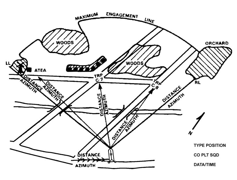
FM 3-22.34
card follows the same procedures provided for the standard range card, but the weapon symbol must be used to indicate the location of the weapon position. The range card must include the following eight items:
• Weapon symbol.
• Sector of fire.
• Maximum engagement line.
• Range and azimuth to TRP/ATEA.
• Dead space.
• Distance and azimuth from a known point.
• Magnetic north arrow.
• Data section.
Figure D-12. Expedient range card.
D-10
FM 3-22.34(FM 23-34)
APPENDIX E
SAFETY
Units should develop local directives and SOPs that include individual responsibilities, safety requirements, proximity limits for personnel and explosives, location and sequence of operations, equipment required for handling munitions, and protection for troops. Individual responsibility for operations involving explosives must be designated. Troops must not tamper with the encased missiles other than to remove the forward handling ring and dust cover.
Because of the danger to troops from the backblast, extreme care must be used in all phases of training. Emphasize this danger from the first stage of training. Conduct all crew tasks, position and tracking exercises, and firings with the simulation round as though missiles were being fired.
E-1. SAFETY
PRECAUTIONS
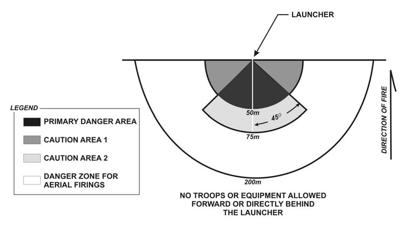
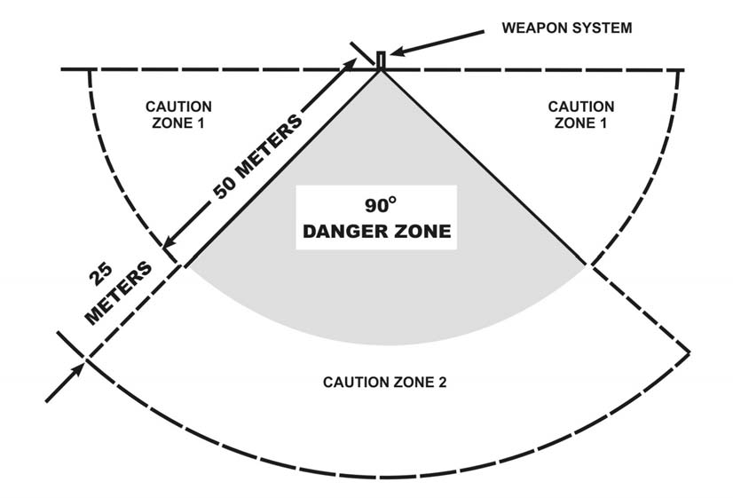
The surface danger zone for any firing range consists of a firing area, a target area, impact area, and danger areas surrounding these locations (Figure E-1). An additional area for occupation by personnel during firings may also be required. The shape and size of the surface danger zone varies with the type of missile or rocket being fired. (Refer to DA Pam 385-63 for dimensions.)
a. The primary danger area is a 90-degree cone with a 50-meter radius. The apex of the cone is centered at the rear of the missile launcher. Serious casualties or fatalities are likely to occur to anyone in the area during firing. Hazards include launch motor blast, high noise levels, overpressure, and debris.
b.
Caution area 1 extends radially from each side of the primary danger area to the firing line with a radius of 50 meters. Permanent hearing damage could occur to personnel without adequate hearing protection in this area during firing. The hazards are high noise levels and overpressure.
c.
Caution area 2 is an extension of the primary danger area with the same associated hazards and personnel protection required. The radius of this area is 75 meters.
d.
The
200-meter zone is the danger area for aerial firings 15.25 meters or more above ground level.
e. TOWs will not be fired from buildings or bunkers, or within 100 meters of a vertical or nearly vertical backstop (IAW DA Pam 385-63).
WARNING
All crew members must wear V-51R (or
equivalent) earplugs that have been fitted by
qualified medical personnel. Failure to use the
proper earplugs during missile firing could cause
serious injury.
E-1
FM 3-22.34
Figure E-1. Surface danger zone for firing basic TOW, TOW 2A, and TOW
2B missiles.
E-2. MISSILE
HANDLING
PRECAUTIONS
Improper handling of the encased missile may damage the components and cause malfunctions when the missile is launched. If the encased missile is dropped, the end handling rings and the launch container may be damaged. If the missile has been damaged or there is damage to the launch container (other than minor deformation of handling rings), the encased missile should be returned to the ammunition unit for inspection and disposition.
E-3.
SIGHTING AND AIMING PRECAUTIONS
Gunners must not look at the sun or bright lights while sighting through the daysight tracker; serious eye burn could result. They must not look through the daysight tracker at an air field test set on the control tower unless the distance between the daysight tracker and the test set is more than 300 feet.
E-4.
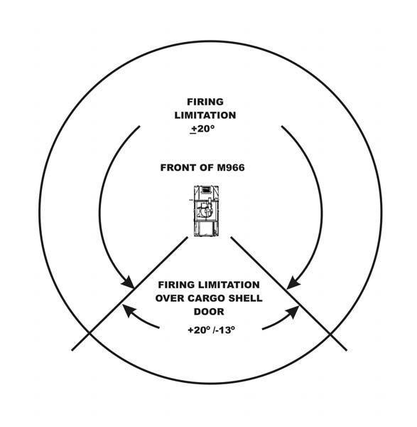
FIRING ANGLE LIMITATIONS
Azimuth and elevation firing angles are limited by the traversing unit, the vehicle, and other external restrictions. All elevation angles are referenced to the horizontal plane of the traversing unit. All azimuth angles are referenced to the long axis of the vehicle and depend on whether the launch tube points over the front or rear of the vehicle. The other reference line is the line-of-sight from the TOW to the target.
E-2
FM 3-22.34
WARNING
At angles greater than 20 degrees above ground
level, hazards to the gunner may exist in the
overpressure waves and debris caused by the
backblast during training. Do not use angles
greater than 20 degrees.
a. When the TOW is tripod-mounted, a 360-degree lateral track is possible, because the traversing unit is not restricted in azimuth. Mechanical stops limit the elevation angle coverage to 20 degrees below and 30 degrees above the horizontal plane. Before the missile is fired, the line-of-sight angle should be estimated at the expected time of launch and throughout the expected missile flight time. The firing position should be changed or a different target selected if an expected line-of-sight angle exceeds the firing limitation angle.
b. The firing angle limitations of the TOW carriers are as shown in Figure E-2.
Figure E-2. M966-mounted TOW firing angle limitations.
E-3
FM 3-22.34
E-5.
SAFETY PRECAUTIONS FOR MILES
The gunner must follow these safety precautions:
a. Do not load an ATWESS cartridge until ready to fire. If the target is lost, remove the ATWESS cartridge from the firing chamber before moving. (Gloves are recommended when loading or unloading the ATWESS cartridge.)
b. Before pulling the PULL-TO-ARM switch, always check to ensure no personnel or equipment (antennas) are in the ATWESS danger zone. This zone extends for 75
meters behind the ATWESS firing chamber and covers an arc 90 degrees wide (Figure E-3).
c. Never view the laser being fired through stabilized optics, such as binoculars or telescopic weapon sights, when within 75 meters of the transmitter.
Figure E-3. ATWESS danger zone.
E-4
FM 3-22.34
E-6.
SAFETY PRECAUTIONS FOR THE TOW GUNNERY TRAINER
The following safety precautions must be observed when using the TGT.
DANGER
THIS EQUIPMENT USES HIGH VOLTAGE TO
OPERATE. NEVER USE UNGROUNDED
EXTENSION CORDS, UNGROUNDED ADAPTERS,
OR ANY UNGROUNDED OUTLET TO CONNECT
THE TGT. DEATH ON CONTACT MAY RESULT IF
PERSONNEL FAIL TO OBSERVE SAFETY
PRECAUTIONS.
a. Use two people to lift the instructor console. The console is heavy and lifting with only one man could result in serious injury.
b. Do not attempt to open shipping cases before pressing air pressure release valves on side of cases. Serious injury to personnel could result from opening cases with high pressure inside.
c. Turn off the power to the TGT trainer and disconnect the wall outlet plug before beginning cleaning procedures.
E-7.
SAFETY PRECAUTIONS FOR THE TOW FIELD TACTICAL TRAINER
The following safety precautions must be observed when using the TFTT.
a. The laser light emitted by the TFTT is considered eye safe, but suitable precautions must be taken to avoid possible eye damage from overexposure to this radiated energy. The preface to TM 9-6920-453-10 and the laser range safety procedures in DA Pam 385-63 and TB MED-279 discuss these precautions.
b. The M80 blast simulator used with the TFTT can cause death or injury. Observe the precautions listed in the preface of TM 9-6920-453-10.
c. To avoid personnel injury and equipment damage, four people are needed to lift and carry each shipping container.
DANGER
THIS EQUIPMENT USES HIGH VOLTAGE TO
OPERATE. DEATH ON CONTACT MAY RESULT IF
PERSONNEL FAIL TO OBSERVE THE SAFETY
PRECAUTIONS LISTED IN TM 9-6920-453-10.
E-5
FM 3-22.34(FM 23-34)
APPENDIX F
TOW TRAINING DEVICES
For many years TOW training devices consisted of the M70-series training sets and MILES TOW equipment. Recently, the Precision Gunnery Training System (PGTS) was fielded. PGTS consists of two systems: an indoor trainer and an outdoor trainer. The TOW Gunner Trainer (TGT) is the indoor system and the TOW Field Tactical Trainer (TFTT) is the outdoor system. The TGT will be used in place of the M70 to qualify individual gunners and for additional sustainment training as needed. The TFTT will be used in place of the M70 for outdoor tracking sustainment and in place of MILES when conducting Tables 5 through 12
of the TOW Training Tables.
MILES TOW equipment is the most realistic device available for simulating tactical engagements. It is valuable in maneuver training exercises and Army training and evaluation programs. However, MILES
TOW is not a precision gunnery trainer and should not be used to train gunner tracking skills.
Section I. MULTIPLE-INTEGRATED LASER ENGAGEMENT SYSTEM
MILES is a training system used in force-on-force training and in FTXs. Commanders should use an MPRC to verify MILES equipment before the unit’s rotation to the NTC.
(See gunnery Tables 7 through 12 in Chapter 4 for target arrays.) F-1. COMPONENTS
AND
FEATURES
This paragraph discusses the different components, features, and capabilities of MILES.
a.
Components.
(1) The following are the nine components in the MILES TOW transit case:
• Operator’s manual.
• Two man-worn laser detector sets (halo and harness).
• Two yellow keys.
• TOW laser transmitter/tracker head simulator.
• Missile guidance set adapter.
• Miscellaneous hardware.
• Hook-pile tape pads.
• Control console mounting bracket.
• Collimator adapter bracket.
(2) The following are the ten MILES APC system components packed in the APC
transit case.
• Operator’s manual.
• Control console.
• Laser transmitter for M2.
• Battery box.
• Hardware.
F-1
FM 3-22.34
• Combat vehicle kill indicators.
• Weapon’s keys.
• Cable assembly.
• Combat vehicle laser detector belt segments.
• Man-worn laser detectors.
b.
Features.
Range:
3,750
meters;