This chapter discusses the techniques and procedures of fire control, helicopter engagement, and firing the TOW under NBC and limited visibility conditions in a combat situation. These techniques and procedures greatly enhance the performance of the TOW weapon system in combat and increase its chances of survival.
Section l. FIRE CONTROL MEASURES
This section discusses fire control measures in combat to include target engagement determination procedures, the elements of fire commands, target tracking procedures, and target engagement procedures with the M220A1 and M220A2 TOW launchers.
5-1. TARGET
ENGAGEMENT
DETERMINATION
Mechanized units are trained to use terrain driving techniques to conceal movement, and drivers are taught to move vehicles quickly from one concealed position to another. TOW
gunners and squad leaders must determine the range to a target and determine if the exposure time―the time a vehicle is in an opening between positions―is long enough to allow a missile to reach its target.
a.
Determine if a Target is Within Range. The TOW gunner or squad leader can use the nightsight method or the binocular method to determine if a target is within range.
(1)
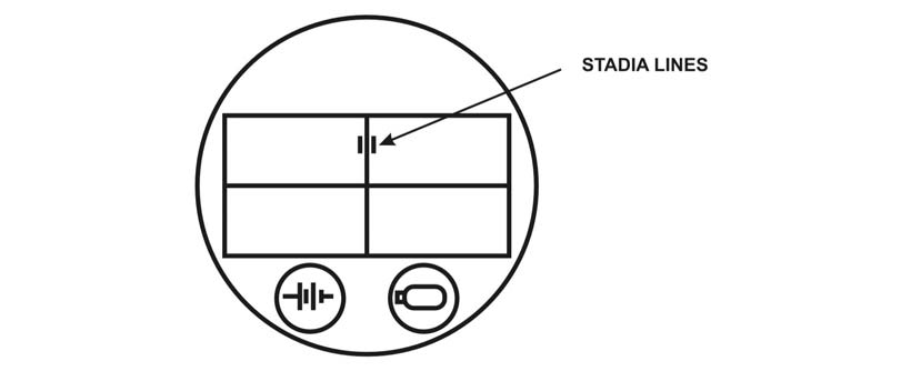
Nightsight Method. The reticle within the nightsight is marked with stadia lines on each side of the vertical crossline and just above the intersection of the vertical and horizontal crosslines (Figure 5-1, page 5-2). Use these stadia lines to determine if a target is within range.
(a) Check to ensure the nightsight is in the narrow field of view.
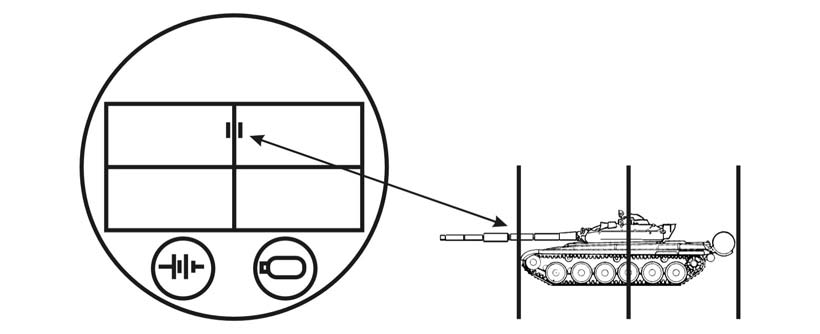
(b) Look at the flank (broadside) of a target. If the ends of the target touch or extend beyond the stadia lines, the target is within range (Figure 5-2, page 5-2).
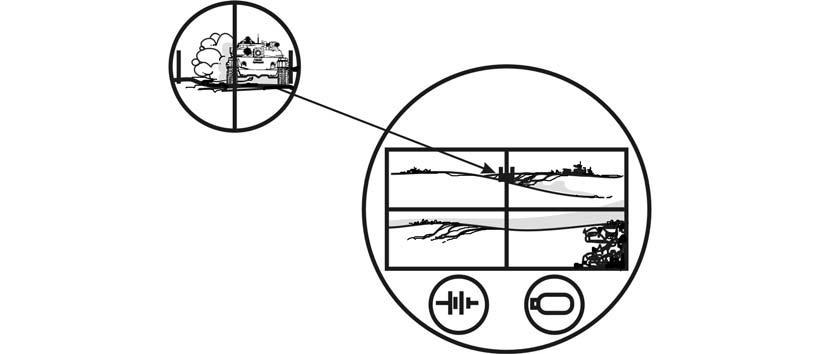
(c) If the target is moving straight or at an angle toward the position, use one-half of the stadia lines. If one side of the vehicle touches one of the stadia lines and the other side of the vehicle touches or extends beyond the vertical line of the crossline, the target is within range (Figure 5-3, page 5-2).
5-1
FM 3-22.34
Figure 5-1. Stadia lines.
Figure 5-2. Target within range.
Figure 5-3. Target moving straight toward or away from position within range.
5-2
FM 3-22.34
NOTE:
When using the stadia lines to determine if a target is within range, keep two things in mind. First, the range is a rough estimate, based on the size of the target. A large vehicle may be out of range when the stadia lines show it to be in range. Second, the stadia lines are designed for a maximum engagement range of 3,000 meters.
(2)
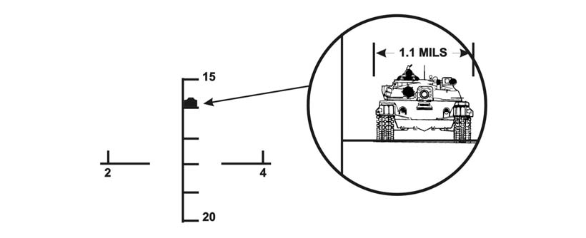
Binocular Method. Use the reticle in binoculars to determine if a target is within range by looking at the length, width, or height of the vehicle. Follow the same procedures when using the M17 and M19 binoculars, even though the reticles differ slightly. The M17 tick marks are only 1.7 mils long while the tick marks on the M19
reticle are 5 mils long (2.5 mils on each side of the horizontal and vertical scales).
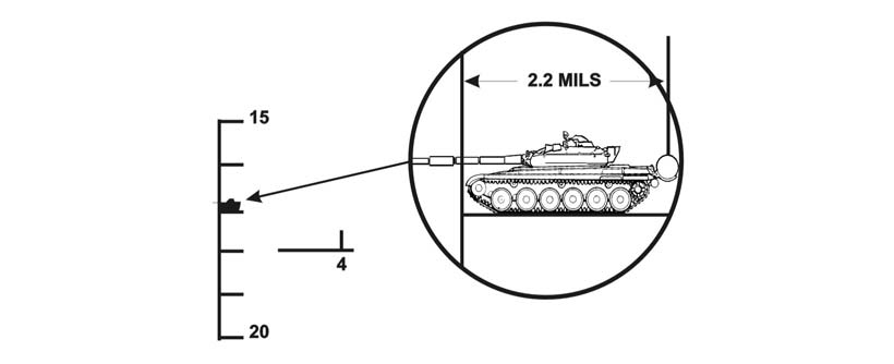
(a) To determine if a target is within range at 3,000 meters based on the length of the target, place the length of the target on the vertical scale. If one-third or more of the vehicle extends beyond the tick mark, the vehicle is in range (Figure 5-4). A vehicle 6.5
meters long will measure about 2.2 mils at 3,000 meters and about 1.7 mils at 3,750
meters.
Figure 5-4. Target within range (flank or oblique) using M17 binoculars.
(b) To determine if a target is within range at 3,000 meters based on the width of the target, place the target on the small tick mark on the vertical scale. If the target covers two-thirds or more of the tick mark, the vehicle is within range (Figure 5-5, page 5-4). A vehicle 3.4 meters wide will measure 1.1 mils at 3,000 meters and .85 mils at 3,750
meters. (Most Warsaw Pact APCs are less than 3.4 meters wide and can be engaged at smaller mil values.)
(c) To determine if a target is within range at 3,000 meters based on the height of the target, place the target on one of the tick marks on the horizontal scale. If the height of the vehicle is one-half or more of the height of one of the tick marks, the vehicle is within range. A vehicle 2.4 meters high (the size of most Warsaw Pact vehicles), will measure
.8 mils at 3,000 meters and .6 mils at 3,750 meters (Figure 5-6, page 5-4).
5-3

FM 3-22.34
Figure 5-5. Target within range (frontal or rear) using M17 binoculars.
Figure 5-6. Target within range based on height.
NOTE:
This method cannot be used if the weapon system is in an elevated firing position or if the lower portion of the target vehicle is hidden by foliage or terrain.
b.
Determine Exposure Time. The half-sight method of determining exposure time is based on a vehicle speed of 35 kilometers per hour (the expected top vehicle speed of armored vehicles on level or gently sloping dry terrain).
(1)
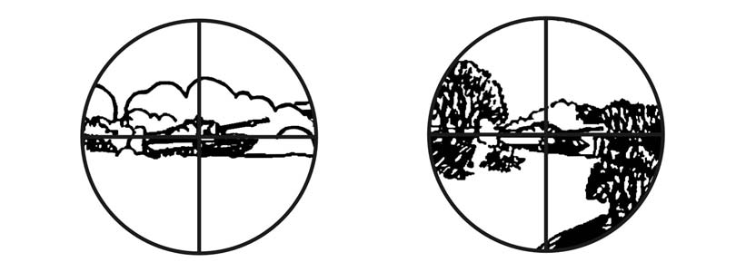
Daysight Tracker Method. Use the crosslines on the daysight tracker to determine the exposure time of a target.
(a) Place the crosslines of the daysight tracker on the center of the visible mass of the vehicle.
(b) If the area between the vertical crossline and the edge of the field of view in the direction of travel is clear of obstruction, the target is engageable (Figure 5-7).
(c) If obstructions appear between the vertical crossline and the edge of the field of view, the time of exposure would not be long enough for the missile flight before the target moved out of sight (Figure 5-7).
5-4
FM 3-22.34
Figure 5-7. Obstruction.
(2)
Nightsight Method. The procedure to determine exposure time is the same for the nightsight as for the daysight tracker, except the nightsight must be set on narrow field of view.
(3)
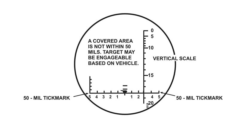
Binocular Reticle Method. Use the reticle in the binoculars to determine the exposure time of a target.
(a) Place the zero tick mark of the horizontal scale at the center of the vehicle.
(b) If the area between the vehicle and the 50-mil tick mark is clear of obstructions in the direction of travel, the target is engageable (Figure 5-8).
Figure 5-8. Binocular reticle method.
5-2. FIRE
COMMANDS
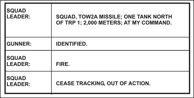
The six elements of a fire command are alert, type of missile, target description, target direction, range, execution, and closing. Whether mounted or dismounted, the elements of the fire command are the same. (Figure 5-9, page 5-6, shows an example of a squad fire command.)
5-5
FM 3-22.34
Figure 5-9. Example of a squad fire command.
a. Alert. The first element of the fire command alerts the crew for an immediate engagement. The squad leader commands, “Squad,” and the gunner begins observing the target area.
b.
Type of Missile. Because a variety of TOW missiles are used and their capabilities vary, a particular type of missile must be specified. A TOW crew in battle will probably have a mix of different missiles and a wide variety of target arrays to engage (see Chapter 1, TOW missile types and configurations). For example, if the target is a BTR-60 or BMP-1, the squad leader may command, TOW 2; if the target is a T-80
with reactive armor, he may command, TOW 2B.
c.
Target Description. The second element identifies the target for the gunner. If several similar targets are present, this element tells the gunner which target to engage first. Most targets can be described by using the terms listed in Table 5-1. Targets that are combinations of the ones listed in Table 5-1, such as a truck mounting a missile system, are identified by combining terms—for example, TRUCK MOUNTING ANTITANK.
When the gunner sees the target, he announces, “Identified.” If multiple targets appear, the commander may specify which target will be engaged by the gunner--for example, FIRST TANK or RIGHT TRACK. (See Appendix H for information on OPFOR/Threat counterpart systems.)
5-6
FM 3-22.34
TARGET ANNOUNCED
AS
Any tank or tank-like vehicle
TANK
Several tanks
TANK FORMATION
Any unarmored vehicle
TRUCK
Any halftrack or armored
TRACK
personnel carrier
Helicopters
CHOPPER
All fixed-wing aircraft
PLANE
Personnel
TROOPS
Any machine gun
MACHINE GUN
Any antitank gun or towed
ANTITANK
artillery piece
A short word or
Any other target
phrase that clearly
describes the target.
Table 5-1. Terms used to describe targets.
d.
Target Direction. If the target is moving, the direction of movement is given after the description to aid the gunner in locating the target. After the gunner is given the location of a target, he can search for the target in the direction of movement. The following methods are also used to help the gunner locate the target.
(1)
Target Reference Point. A TRP is an easily recognizable feature or point on the ground (either natural or man-made) used for identifying targets and controlling fires.
They can be used to designate targets for companies, platoons, sections, and individual weapons. They can also be used to designate the center of an area where the commander plans to distribute or converge the fires of all his weapons. TRPs are usually designated by the company commander or platoon leaders.
(a) Weapons will engage targets from different directions, so compass points (for example, north, east), rather than “right” or “left,” are used when giving directions centered on a TRP.
(b) Deflection from the TRP can be estimated, or it can be measured using the binocular mil scale or the circular reticle on the wide field of view−for example, 5.5
degrees at 1,000 meters is about 100 meters, or 200 meters at 2,000 meters.
(2)
Prominent Features. The commander may give the distance and direction from a prominent feature−for example, FROM HILL SEVEN SIX TWO, LEFT TWO
HUNDRED, or FROM BRIDGE, RIGHT FOUR HUNDRED.
e.
Range. The range is given to help the gunner identify his target and to determine its engageability. The squad or section leader can determine the range to the target using the naked eye, binoculars (mil-relation formula), or reference materials (maps, range cards).
(1)
Naked Eye. One method for using the naked eye to determine range is the football field method. The squad or section leader counts in 100-meter increments, estimating the number of football fields that could fit between the firing position and the target.
5-7
FM 3-22.34
(2)
Binoculars. Binoculars and the mil-relation formula can be used to determine range. To use this method, the squad or section leader must know the width, height, or length of the target. He determines the width, height, or length with the mil scale on the binoculars; substitutes the mil-relation; and computes the range.
(3)
Reference Materials. Maps can be used to determine range by counting the grid lines between the firing position and the target or by adjusting from a known point.
Range cards can also be used to determine the range to the target.
f.
Execution. Two commands are necessary for execution: a preparatory command and a command of execution.
(1) AT MY COMMAND is a preparatory command that warns the gunner not to fire until given the command of execution.
(2) FIRE is the only command of execution used to fire a missile.
g.
Additional Commands. In addition to the six elements of the fire command, some other commands are needed.
(1) The command CEASE TRACKING or CEASE TRACKING, OUT OF ACTION
is issued after seeing the round detonate or when the squad or section leader wants to halt firing.
(a) CEASE TRACKING tells the crew the squad or section leader intends to stay in position and engage another target immediately or when one appears.
(b) CEASE TRACKING, OUT OF ACTION tells the crew the squad or section leader intends to move to another position.
(2) To determine the method of engagement, the section leader (or above) selects a fire pattern depending on the opposing force’s formation. The section leader directs, FRONTAL, DEPTH, or CROSSFIRE, when the gunner is faced with multiple targets.
(3) When the target is identified, the gunner announces, “Identified.”
(4) If the gunner cannot see the target, he announces, “Lost.”
(5) If the gunner cannot identify the target, he announces, “Cannot identify.”
(6) The loader announces, “Backblast clear,” before the command of execution is given.
h.
Repeating Commands. When a crew member fails to hear or understand any element of a fire command, he announces the element in question. For example, if the gunner asks, “Location?” the squad leader repeats the location element such as, “From hill seven six two, west two hundred.”
i. Correcting Errors. To correct an error in a fire command, the squad leader announces, “Correction,” and corrects only the element in error. He completes the command by announcing all elements after the corrected element. He does not try to correct an element that has been needlessly included, such as the direction element. He corrects the omission of an element by announcing “Correction” and then the omitted element. After announcing the omitted element, he completes the command.
j. Commands for the Driver. Although directions to the driver are not part of the fire command, they are given by the squad leader or gunner in short terms.
5-3. TARGET
TRACKING
To track a target, the gunner visually acquires the target through the daysight tracker system of the TOW. He can track the target by either optical or electrooptical means, depending on the system configuration being used and on the visibility conditions.
5-8
FM 3-22.34
a. To track the target, the gunner operates the hand controls on the traversing unit to keep the reticles in the launcher sight aligned with the target. The daysight tracker system is attached to and aligned with the launch tube. The launch tube stabilizes the exit of the missile from the launcher for initial alignment during missile flight. On achieving target alignment, the gunner fires the missile by manually depressing the trigger switch.
Thereafter, all operations are automatic and the gunner’s only task is to maintain alignment of the sight reticle on the target until missile impact.
b. Deviations of the missile from the line-of-sight trajectory are sensed in the launcher sight by infrared means that receive information from infrared radiators attached to the missile. This information is processed in the form of electrical signals to produce error signals proportional to the azimuth and elevation displacements of the missile from the intended trajectory. Correction commands are derived from these error signals and are sent to the missile over the command-link wires, which are dispensed from the missile.
The missile performs corrective maneuvers using aerodynamic control surfaces that deflect in response to the command signals from the launcher. On target impact, a high-explosive, shaped-charge warhead is detonated.
5-4. TARGET
ENGAGEMENT
WITH THE M220A1 (BASIC TOW)
Specific procedures are followed to engage a target with the M220A1.
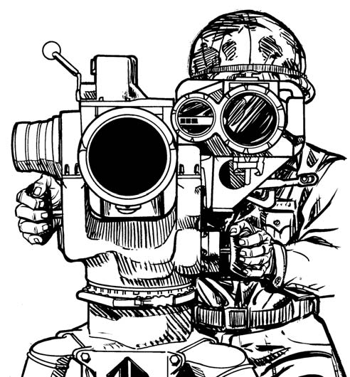
a. Position the eye well into the rubber eyepiece and place both hands firmly on the control knobs (Figure 5-10). Place the body so there is no contact between the shoulder and the encased missile. The only contact with the launcher is with the hands and eye.
Assume a firing position that is comfortable. An uncomfortable position causes muscle tension, which affects the ability to track smoothly.
Figure 5-10. Control knobs.
5-9
FM 3-22.34
NOTE: When firing from the tripod, kneel on one or both knees.
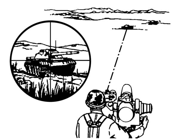
b. Raise the trigger protective cover and establish a smooth tracking rate while keeping the crosshairs on the center of visible mass of the target (Figure 5-11).
Figure 5-11. Crosshairs on the center of visible mass of the target.
c. Move the launch tube left or right by applying a smooth, steady force to both control knobs (pushing one and pulling on the other) and rotating the body from the waist up as the launcher moves. Elevate or depress the launch tube by applying a smooth, steady turning force to both control knobs. Applying pressure to only one control knob, or applying uneven pressure, makes it more difficult to track smoothly. Maintain the same arm, shoulder, and head position throughout an engagement. Any change in body position other than leaning with the controls will cause a jerking motion that could result in grounding of the missile.
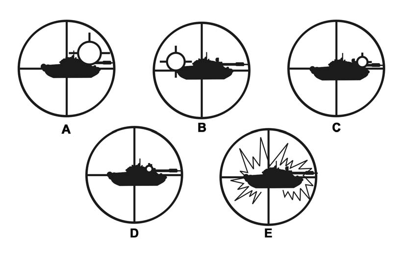
d. Proper breath control is especially important during the first and last 400 meters of missile flight. Improper breathing will cause poor tracking. Take a deep breath and let part of it out; then, press the trigger. After a 1.5-second delay, the missile will launch.
The delayed firing of the launch motor may cause you to flinch or jerk the control knobs if you are not prepared for it. Be prepared for two noises after the trigger is pressed. The first noise is the gyro being activated. While it is not loud, it may cause you to think a misfire has occurred, and you may not be prepared for the next noise. The second noise is the launch motor firing and it is loud. The dust, smoke, heat, and debris from the backblast may cause flinching. When the missile appears in the sight picture, ignore it.
Never try to guide the missile. If distracted, tracking becomes poor and chances of hitting the target are reduced. Continue to track the target at a smooth tracking rate, keeping the crosshairs on the center of visible mass until missile impact (Figure 5-12).
5-10
FM 3-22.34
Figure 5-12. Keep crosshairs on the center of visible mass.
5-5. TARGET
ENGAGEMENT
WITH THE M220A2 (TOW 2)
Specific procedures are followed to engage a target using the M220A2.
a. Looking through the daysight tracker, adjust the focus control until the crosshairs are in focus. (To see the crosshairs clearly, set RETICLE LIGHT switch to ON.) Position the crosshairs on the target, and remove the front lens cover from the nightsight by releasing two latches. Set the ON-OFF-STBY switch to ON. Look through the eyepiece and adjust the diopter adjustment ring to focus the reticle. Ensure the battery monitor light is off. Set the field of view selector to wide field of view, locate the target, and adjus