Sakthivel, S.; Neppolian, B.; Shankar, M.V.; Arabindoo, B.; Palanichamy, M. & Murugesan, V. (2003) Solar photocatalytic degradation of azo dye: Comparison of photocatalytic
efficiency of ZnO and TiO2. Sol. Energy Mater. Sol. Cells, Vol. 77 No. 1, pp.65-82.
Santarelli, F. & Smith, J.M. (1974) Rate of photochlorination of liquid n-heptane. Chem. Eng.
Commun., Vol. 1, pp. 297-302.
Sathishkumar, P.; Sweena, R. & Wu, J.J. (2011) Anandan, S. Synthesis of CuO-ZnO
nanophotocatalyst for visible light assisted degradation of a textile dye in aqueous
solution. Chem. Eng. J., Vol. 171 No. 1 pp. 136-14.
Sayama, K.; Hayashi, H.; Arai, T.; Yanagida, M.; Gunji, T. & Sugihara, H. (2010) Highly
active WO3 semiconductor photocatalyst prepared from amorphous peroxotungstic
acid for the degradation of various organic compounds. Appl. Catal. B: Environ.,
Vol. 94 No. 1-2 pp.150-157.
Schechter, R.S. & Wissler, E.H. (1960) Photochemical reactions in an isothermal laminarflow chemical reactor. Appl. Sci. Res., Vol. 9 No. 1, pp. 334-344
Shirotsuka, T. & Nishiumi, H. (1971) Theoretical basis for making an apparatus for
photochemical reactions. Kagaku Kogaku, Vol. 35, pp. 1329-1338.
176
Applied Computational Fluid Dynamics
Song, S.; Xu, L.; He, Z.; Chen, J.; Xiao, X. & Yan, B. (2007) Mechanism of the photocatalytic degradation of C.I. reactive black 5 at pH 12.0 using SrTiO3/CeO2 as the catalyst.
Environ. Sci. Technol., Vol. 41 No. 16 pp. 5846-5853.
Sopyan, I.; Watanabe, M.; Murasawa, S.; Hashimoto, K. & Fujishima, A. (1996) An efficient TiO2 thin-film photocatalyst: photocatalytic properties in gas-phase acetaldehyde
degradation. J. Photochem. Photobiol., Vol. 98 No. 1-2. pp. 79-86.
Taghiour, F. & Mohseni, M. (2005) CFD simulation of UV photocatalytic reactors for air
treatment. AIChE J., Vol. 51 No. 11 pp. 3039-3047.
Tang, W.Z. & Huang, C.P. (1995) Photocatalyzed oxidation pathways of 2,4-dichlorophenol
by CdS in basic and acidic aqueous solutions. Water Res., Vol. 29 No. 2 pp. 745-756.
Teramura, K.; Tanaka, T.; Kani, M.; Hosokawa, T. & Funabiki, T. (2004a) Selective photo-
oxidation of neat cyclohexane in the liquid phase over V2O5/Al2O3. J. Mol. Catal. A:
Chem., Vol. 208 No. 1-2 pp. 299-305.
Teramura, K.; Tanaka, T.; Hosokawa, T.; Ohuchi, T.; Kani, M. & Funabiki, T. (2004b)
Selective photo-oxidation of various hydrocarbons in the liquid phase over
V2O5/Al2O3. Catal. Today, Vol. 96 No. 4 pp. 205-209.
Torres-Martínez, C.L.; Kho, R.; Mian, O.I. & Mehra, R.K. (2001) Efficient photocatalytic degradation of environmental pollutants with mass-produced ZnS nanocrystals. J.
Colloid Interface Sci., Vol. 240 No. 2 pp. 525-532.
Van Grieken, R.; Aguado, J.; López-Muoz, M.J. & Marugán, J. (2002) Synthesis of size-
controlled silica-supported TiO2 photocatalysts. J. Photochem. Photobiol. A:
Chemistry, Vol. 148 No. 1-3, pp. 315-322.
Vincent, G.; Schaer, E.; Marquaire, P.-M. & Zahraa, O. (2011) CFD modelling of an annular reactor, application to the photocatalytic degradation of acetone. Process Saf.
Environ. Prot., Vol. 89 No. 1 pp. 35-40.
Waldner, G.; Brüger, A.; Gaikwad, N.S. & Neumann-Spallart, M. (2007) WO3 thin films for
photoelectrochemical purification of water. Chemosphere, Vol. 67 No. 4 pp. 779-784.
Wang, K.-H.; Tsai, H.-H. & Hsieg, Y.-H. (1998) The kinetics of photocatalytic degradation of trichloroethylene in gas phase over TiO2 supported on glass beads. Appl. Catal. B:
Environ., Vol. 17 No. 1-2 pp. 25-36.
Wilkes, J.O. Fluid mechanics for chemical engineers with microfluidics and CFD, 2nd ed.
Prentice Hall: NJ, 2005.
Williams, J.A. & Ragonese, F.P. (1970) Asymptotic solutions and limits of transport
equations for tubular flow photoreactors. Chem. Eng. Sci., Vol. 25 pp. 1751-1759.
Williams, J.A. (1978) The radial light intensity profile in cylindrical photoreactors. AIChE J., Vol. 24 pp. 335-338.
Xu, Y.; Zheng, W. & Liu, W. (1999) Enhanced photocatalytic activity of supportedTiO2:
Dispersing effect of SiO2. J. Photochem. Photobiol. A: Chemistry, Vol. 122, No.: 1, pp.
57-60.
9
Aerodynamic Design of the Vertical Takeoff
Hopper Concept of Future Launchers
Preparatory Programme
Giuseppe Pezzella
Italian Aerospace Research Centre - CIRA, via Maiorise, Capua
Italy
1. Introduction
In the frame of the Future Launchers Preparatory Program, carried out by the European
Space Agency, the vertical take-off (VTO) Hopper - reusable launch vehicle concept is
investigated (Guédron, 2003) (Kauffmann, 2006).
The VTO Hopper is a reusable, winged sub-orbital single stage vehicle, featuring a circular
cross-section, designed for vertical take-off. The launch vehicle is composed of a reusable
booster (the Hopper) and an expendable upper stage, mounted on top of it (Pezzella et al.,
2009).
After the staging at suborbital altitude (> 130 km), the reusable booster will follow a ballistic arc trajectory, will re-enter the Earth’s atmosphere, and will then perform a downrange
landing (Pezzella et al., 2009).
The upper stage will deliver a payload up to 8 Mg in geostationary transfer orbit.
In this chapter the current aerodynamic analysis related to the launcher design is described.
The goal was to define the aerodynamic data-base of the vehicle in order to provide the
necessary input for the Flight Mechanics analysis.
Different design approaches were adopted in this work. In fact, aerodynamic analysis has
been performed starting from engineering based methods, in order to rapidly accomplish
the preliminary aerodynamic database to generate a number of possible re-entry trajectories, able to fulfill the program requirements. To do these analyses, a three dimensional (3-D)
panel methods code, based on the simplified Newtonian approach and local inclination
methods typical of hypersonics, was employed (Bertin, 1994).
Increasing the order of complexity, a number of detailed computational fluid dynamics
(CFD) analyses have been carried out to more deeply characterize the hypersonic re-entry
environment of the vehicle.
To this end, 3-D Euler and Navier-Stokes numerical flowfield computations were performed
at different Mach numbers and angles of attack, at the most critical flight conditions of the vehicle descent trajectory.
In the chapter, qualitative summaries of the results are given for each aerodynamic force
and moment coefficient as function of Mach number, Reynolds number and angle of
attack.
178
Applied Computational Fluid Dynamics
2. The VTO-Hopper concept
The VTO-Hopper is one of the possible future launch systems which are investigated within
the Future Launchers Preparatory Program (FLPP) (Tomatis et al., 2006). The vehicle
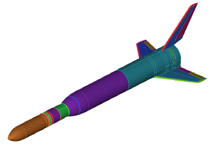
architecture is shown in Fig. 1 (Pezzella et al., 2010).
Fig. 1. The VTO-Hopper concept in ascent (left) and descent Configuration (right)
The vehicle concept is a two stage space transportation system comprising a fully reusable
first stage, which starts vertically and performs a parabolic suborbital trajectory, and a
dispensable second stage, carrying the payload.
The first stage, designed as a winged reentry body, will return to Earth to a point
downrange of the launch site and land horizontally.
The current shape features a circular cross section of the body fuselage with wings in low
position and a vertical fin. The circular shape has been adapted in order to introduce body
flap.
2.1 The mission scenario
The design trajectory of the VTO-Hopper on which the aerodynamic design activities were
performed is depicted in Fig. 2.
It shows, in the upper side, the altitude versus time spent to reentry starting at entry
interface (e.g. 120 Km), while in lower part the Mach and angle of attack (AoA) profiles
versus time to reentry are reported.
3. Description of design approach and used tools
A summary review of the aerodynamic characteristics of the VTO-Hopper concept is
performed. These evaluations were aimed only to carry out a preliminary aerodynamic
database (AEDB) for such configuration, compliant with a phase-A design level (Pezzella
et al., 2008). The range between Mach 2 and Mach 20 was analyzed, with the goal to
provide aerodynamic database for the flight mechanics analyses. The aerodynamic
coefficients have been provided as a function of Mach number, and angle of attack (zero
sideslip angle and no active control surface deflections) according to the space-based
design approach (Pezzella et al., 2009).
Aerodynamic Design of the Vertical Takeoff
Hopper Concept of Future Launchers Preparatory Programme
179
This approach dictates the generation of a complete data set as function of a number of
independent parameters (i.e. M, Re, α, ). Then, by using engineering based design, one
can rapidly develop aerodynamic database as a function of the freestream parameters in a
matter of hour (Bertin, 2004).
In the present analysis only continuum regime (supersonic and hypersonic speed ranges)
with the air modeled as perfect gas has been studied.
It is worth to underline, however, that at high altitudes the rarefaction and real gas effects should be taken into account when the vehicle is flying at high Mach number, being the
AEDB strongly affected by both these aspects (Bertin, 2004). Therefore, for the prosecution
of vehicle design (i.e. phase B and C) more reliable design methodologies are mandatory.
In the following paragraphs the tools used for the analysis are described.
140
120
100
80
m)
(k
de
tulti 60
A
40
20
0
0
200
400
600
800
1000
1200
Time to reentry (s)
20
60
18
50
Mach No.
16
AoA
14
40
12
(-)o
eg)d
N 10
30
(A
achM
Ao
8
20
6
4
10
2
0
0
0
200
400
600
800
1000
1200
Time to reentry (s)
\
Fig. 2. The VTO-Hopper design trajectory in Altitude-time map (up) and Mach no/AoA vs
time to reentry (down)
180
Applied Computational Fluid Dynamics
3.1 Aerodynamic analysis tools
The VTO-Hopper has a number of extreme loading flight conditions for which analyses are
required. It must return from orbit, fly trimmed throughout hypersonic and supersonic
regimes until landing is gained, and withstand severe aeroheating. An accurate
aerodynamic analysis of all these flight conditions is very complex and time consuming, and
is not compatible with a Phase A design study, in which fast predicting methods are
mandatory (Pezzella, 2011). Therefore, the evaluations of the vehicle AEDB and of its
reentry aerothermal environment were mainly performed by means of engineering tools,
while a limited number of more advanced CFD computations were performed in order to
verify the attained accuracy and to focus on some critical design aspects not predictable
with simplified tools. Engineering based aerodynamic and aerothermodynamic analyses
were extensively performed by using a 3D Panel Methods code developed by CIRA (SIM–
Surface Impact Method) in the frame of its research activities on preliminary design of
reentry vehicles (Pezzella, 2011). This tool at high supersonic and hypersonic speeds is able to accomplish the aerodynamic and aerothermodynamic analyses of a complex reentry
vehicle configuration by using simplified approaches as local surface inclination methods
and approximate boundary-layer methods, respectively. Surface Impact Methods (SIM),
typical of hypersonics, are: Newtonian, Modified Newtonian, Tangent cone and Tangent
Wedge theories (Bertin, 2004).
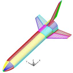
In Fig. 3 is shown a typical mesh surface of VTO-Hopper that has been used for the
engineering level computations (Pezzella, 2011).
On the other hand the numerical code used to carry out the CFD analyses of the VTO
vehicle concept is the CIRA code H3NS (Pezzella et al., 2009). It solves the flowfield
governing equations, including chemical and vibrational non-equilibrium, with a finite
volume approach; a flux difference splitting upwind scheme is used for the convective
terms, with a 2nd order ENO-like reconstruction of cell interface values. The viscous fluxes are calculated by central differencing, i.e. computing the gradients of flow variables at cell interfaces by means of Gauss theorem. Time integration is performed by employing an Euler
Forward scheme coupled with a point implicit treatment of the species and vibration
energies source terms. Also a parallel version of the code is currently available. Several
boundary conditions are available for the viscous computations, including different
catalycity models and the possibility to assign at the wall a fixed temperature or a radiative equilibrium condition (Pezzella et al., 2009).
Z
X
Y
Fig. 3. Example of surface mesh used for engineering analysis
Aerodynamic Design of the Vertical Takeoff
Hopper Concept of Future Launchers Preparatory Programme
181
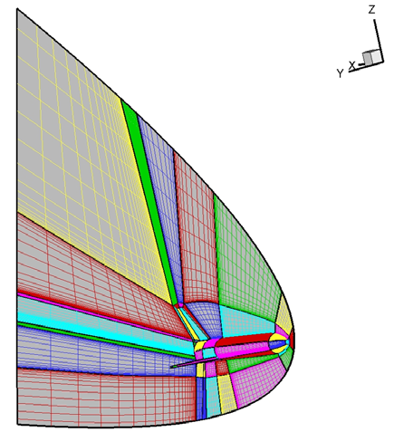
CFD computations have been carried out on a multiblock structured grid similar to that shown in Fig. 4 that is generated with the commercial tool ICEM-CFD. The grid used for Euler
calculations has consisted of 62 blocks for an overall number of 829000 cells (half body).
Fig. 4. Example of multiblock CFD domain. Mesh on symmetry plane and vehicle surface
(left). Mesh on vehicle surface (right)
The grid is tailored for the freestream conditions of the trajectory check points, that are
summarized in Table 1.
The distribution of surface grid points was dictated by the level of resolution desired in
various areas of vehicle such as stagnation region and base fillet, according to the
computational scopes. Grid refinement in strong gradient regions of flowfield was made
through a solution adaptive approach.
4. Aerodynamic analysis and features of the VTO-Hopper vehicle in ascent
and descent configuration
The VTO Hopper launcher consists of a rather conventional slender missile-like vehicle with
a small delta planform wing (37.2° leading edge sweep) at very rear position and a central
vertical stabilizer, as basic shape. The concept shows a circular cross section with a loft fillet on the belly side to accommodate the wing (blended wing body interface). The Wing
geometry data are: root/tip chord: 11.70 m / 4.914 m; half span b/2: 11.63 m; wing leading /
trailing edge angle: 37.23° / 10°; apex longitudinal position (from the base of the fuselage): 11.70 m; angle of incidence (setting) of the wing: 3°; dihedral: 3°.
With these data the wing surface is equal to 193.23 m2.
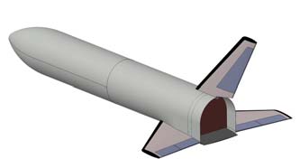
The VTO-Hopper is characterized by a clean aerodynamic configuration, (i.e. controls in
neutral position), that is depicted in Fig. 5 for ascent and descent flight.
182
Applied Computational Fluid Dynamics
Fig. 5. Vehicle clean aerodynamic configuration for ascent (up) and descent flight (down)
The aerodynamic controls comprise rudders on the vertical tail, elevons and ailerons on the
wings, and a body flap underneath the main engines in order to provide maneuverability
and longitudinal stability during atmospheric descent. At hypersonic speeds a surface
behind the vehicle centre of gravity (CoG) balances the nose up pitching moment typical of
such kind of vehicle configuration at hypersonic speeds (Bertin, 2004). Normalizing the
vehicle overall dimensions by fuselage length (Lref=58.8 m), the VTO-Hopper is
characterized by the following normalized reference data:
B’ (wing span)=0.54;
S’ (reference surface)=0.056;
X’MRP=0.69; Y’MRP=0; Z’MRP=0;
In the following, the aerodynamic analysis is shown in term of lift (CL), drag (CD) and pitching moment (CMy) coefficients which are calculated according to Eq. 1 and Eq. 2, respectively.
F
C
i
i L, D
(1)
i
1 v2 S
2
ref
M
C
j
j Y
(2)
M j
1 v2 L S
ref
ref
2
4.1 The VTO-Hopper aerodynamic for ascent flight
The aerodynamic performance of VTO Hopper in ascent flight has been carried out starting
from the results summarized in (Guédron et al., 2003) for the French concept RFS. The
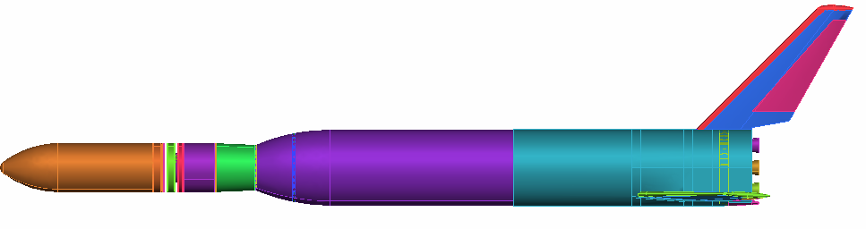
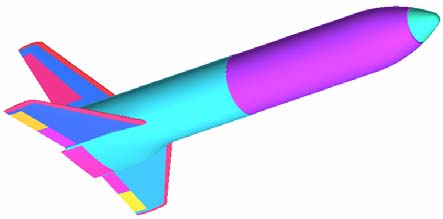
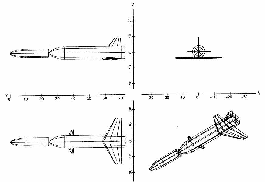
geometry of RFS launcher configuration with booster, expendable upper stage and fairing is
shown in Fig. 6.
Aerodynamic Design of the Vertical Takeoff
Hopper Concept of Future Launchers Preparatory Programme
183
Fig. 6. RFS Configuration. Dimensions in [m] (Guédron et al., 2003)
As one can see this vehicle concept is characterized by an aerodynamic configuration very
close to the VTO one, except for canard flight control surfaces mounted in front of launcher.
Therefore, the preliminary ascent AEDB of the VTO-Hopper has been built by properly
scaling the RFS’s AEDB on the base of VTO aerodynamic configuration features.
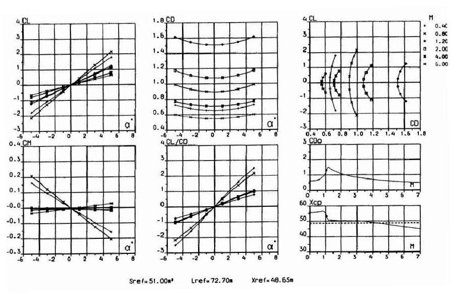
For the RFS launcher configuration the aerodynamic coefficients are summarized in Fig. 7
(Guédron et al., 2003).
Fig. 7. Aerodynamic coefficients for ascent flight of RFS launcher (Guédron et al., 2003)
184
Applied Computational Fluid Dynamics
Starting from those data the preliminary AEDB of the VTO-Hopper is synthesized in the
following Fig. 8 through Fig. 10.
0.8
0.6
0.4
M=0.4
t
0.2
en
M=0.8
fici
M=1.2
ef
0.0
o
M=2.0
ift C
M=4.0
-0.2
L
M=6.0
-0.4
-0.6
-0.8
-6
-4
-2
0
2
4
6
AoA (deg)
Fig. 8. Lift coefficients vs AoA for ascent flight
0.45
0.40
0.35
0.30
t
M=0.4
en
M=0.8
0.25
ffici
M=1.2
eo 0.20
M=2.0
Cg
M=4.0
raD 0.15
M=6.0
0.10
0.05
0.00
-6
-4
-2
0
2
4
6
AoA (deg)
Fig. 9. Drag coefficients vs AoA for ascent flight
Aerodynamic Design of the Vertical Takeoff
Hopper Concept of Future Launchers Preparatory Programme
185
0.08
0.06
tn 0.04
iec
ffie 0.02
o
M=0.4
C
nt
M=0.8
e
0.00
M=4.0
M=6.0
-0.02
ng momhi -0.04
itcP
-0.06
-0.08
-6
-4
-2