t
en
-1.0
fficie
t con -1.5
me
CIRA engineering-SIM
o
m
CFD-Euler
ingh -2.0
tc
Pi
-2.5
-3.0
-3.5
Angle of Attack (deg)
Fig. 29. Pitching moment coefficient vs AoA. Comparison between SIM and CFD Euler at
M=16 (error bar for 10%).
As clearly evident, results of engineering based approach and CFD computations compare
very well at each Mach number and AoA considered. The maximum difference was found
at Mach 16 and AoA=50 deg even if it is comprised within an error bar of 10%.
6. Concluding remarks
Preliminary hypersonic aerodynamics dataset for the VTO-Hopper, under development as
launcher system concept within the Future Launchers Preparatory Program of European Space Agency, have been carried out in the present chapter.
The Hopper configuration is a missile-like re-entry body designed for performing a
suborbital, parabolic trajectory with a horizontal landing.
A possible re-entry mission profile has been considered as design trajectory with respect to the aerodynamics of the vehicle concept. Hopper aerodynamics review analyses refer to
Mach number ranging from 2 to 20 and AoA from 0 to 50 deg, which are conditions
covering the whole reentry scenario of the vehicle concept (space-based design approach).
It must be underlined, however, that present analysis has not been obtained by means of accurate and more reliable CFD computations. Therefore, a proper margin should be
adopted in recognizing vehicle aerodynamics.
Overall available results highlight that the difference between eulerian CFD and engineering based design is smaller than 10%, thus confirming that surface impact method (SIM)
represent a reasonable preliminary design approach in order to accomplish the aerodynamic
characterization of a re-entry vehicle across the hypersonic regime.
Note, in conclusion, that in the next phases of VTO-Hopper design, further analyses have to
be performed on specific topics in order to increase the reliability of the aerodynamic
Aerodynamic Design of the Vertical Takeoff
Hopper Concept of Future Launchers Preparatory Programme
199
database and to reduce the design margins. In particular, the attention has to be focused on real gas and rarefaction effects, as well as shock-shock interactions and laminar-to-turbulent transition. The real gas effects can be important because, during atmospheric re-entry,
dissociation and ionization processes take place in the shock layer, which can have an
influence on the aerodynamic coefficients. Real gas effects are expected to affect stability and control derivatives of vehicle, in particular its pitching moment, as highlighted by first U.S
Space Shuttle reentry (STS-1) where an unexpected higher nose-up pitching moment
required a body-flap deflection twice the one predicted by the pre-flight analyses to trim the Orbiter. Moreover, real gas effects cause a shock that lies closer to the vehicle with respect to the position that would characterize a perfect gas case. These effects obviously occur only at higher Mach numbers.
Further, regarding to the aerodynamic coefficients, it is well known that at very high
altitude, when the Reynolds number decreases and rarefaction effects are present, there is a strong increase of the drag coefficient and a consequent reduction of the maximum
efficiency. Another aspect that has to be considered is the interaction of the bow shock with the shock generated by the wing. It is an important phenomenon that has to be investigated
because it can have a significant impact on the local pressure and heat flux distribution.
7. References
Bertin, John J., Hypersonic Aerothermodynamics, AIAA Education Series, 2004.
Kauffmann, J. Future European Launch Systems in the FLPP Overview and Objectives. 57th International Astronautical Congress, 2-6 Oct. 2006, Valencia, Spain. IAC-06-D2.4.05.
Guédron, S., Prel, Y., Bonnal, C., Rojo, I., RLV Concepts and Experimental Vehicle System Studies: Current Statuse, 54th International Astronautical Congress, 29 Sept.-3 Oct.
2003, Bremen, Germany, IAC-03-V.6.05.
Pezzella, G., Marini, M., Roncioni, P., Kauffmann, J., Tomatis, C., Preliminary Design of Vertical Takeoff Hopper Concept of Future Launchers Preparatory Program, Journal of
Spacecraft and Rockets 2009. ISSN 0022-4650 vol.46 no.4 (788-799) doi:
10.2514/1.39193
Pezzella, G., Marini, M., De Matteis, P., Kauffmann, J., Dapra, A. and Tomatis, C.,
Aerothermodynamic Analyses of Four Reusable Launchers in the Framework of ESA
Future Launchers Preparatory Programme. Aerotecnica Missili & Spazio (The Journal of Aerospace Science, Technologies & Systems). Vol. 89 No. 1 January 2010.
Pezzella, G., Aerodynamics and Aerothermodynamics Analysis of Three Winged Re-Entry Vehicle Concepts. International Journal of Engineering and Allied Sciences (IJEAS), Volume
(1): Issue (1). 2011. ISSN 2248-8568.
Pezzella, G., Aerodynamic and Aerothermodynamic Trade-off Analysis of a Small Hypersonic Flying Test Bed. Acta Astronautica. doi:10.1016/j.actaastro.2011.03.004. Volume (69): Issue (3-4). 2011. ISSN (0094-5765): pag.: 209-222.
Pezzella, G., Preliminary Aerodynamic and Aerothermodynamic Assessment of the VTO Hopper Booster. ISRN Mechanical Engineering. Volume 2011, Article ID 215785, 15 pages.
doi:10.5402/2011/215785.
Pezzella, G., Marini, M., Roncioni, P., Kauffmann, J., Tomatis, C., Aerodynamic and
Aerothermodynamic Evaluation of the VTO Hopper Concept in the Frame of ESA Future
Launchers Preparatory Program, 15th AIAA International Space Planes and
200
Applied Computational Fluid Dynamics
Hypersonic Systems and Technologies Conference. Apr. 28-1, 2008. Dayton, Ohio
(USA), paper AIAA-2008-2639.
Pezzella, G., Kauffmann, J., Dapra, A., Tomatis, C., An Italian Contribution to the Next Generation Launcher in the Framework of ESA Future Launchers Preparatory Programme,
XX AIDAA Congress, Milan, Italy, June 29-July 3, 2009.
Tomatis, C., Bouaziz, L., Franck, T., Kauffmann, J., RLV Candidates for European Future
Launchers Preparatory Programme. 57th International Astronautical Congress, 2-6 Oct.
2006, Valencia, Spain. IAC-06-D2.2.07.
Viviani, A., Pezzella, G., Heat Transfer Analysis for a Winged Reentry Flight Test Bed, International Journal of Engineering (IJE), Volume (3): Issue (3). 2009. ISSN: 1985-2312.
10
Fluid-Structure Interaction
of a Radial Turbine
Zied Driss, Sarhan Karray,
Hedi Kchaou and Mohamed Salah Abid
University of Sfax (US)
National Engineering School of Sfax (ENIS)
Laboratory of Electro-Mechanic Systems (LASEM)
Tunisia
1. Introduction
Fluid-structure interaction (FSI) plays a very important role in many industrial
applications as diverse as aerospace, automotive, biomedical, civil and nuclear
engineering. In the coupling between fluid and structure, the deforming structure
modifies the boundary conditions for the fluid due to the motion of the fluid boundary.
At the same time, the fluid flow causes varying loading conditions on the structure.
Though efficient solvers for both the fluid and the structural dynamics exist, the
development of tools for modelling various fluid-structure interaction problems remains a
challenge. In order to describe FSI problems, an exchange of data has to take place
between the fluid and structural fields. Based on this data exchanged, the methods for
solving fluid-structure interaction problems can be divided into monolithic and
partitioned couplings. For example, we can mention the researcher of Bobovnika et al.
(2005). In this paper, the authors are interested to couple a finite-volume model to a finite-element model of the straight-tube Coriolis flowmeter. Michler et al. (2004) have
developed a monolithic approach to fluid-structure interaction. Piperno and Farhat (2001)
are interested to partitioned procedures for the transient solution of coupled aeroelastic
problems. Sternel et al. (2008) are developed an efficiency and accuracy of fluid-structure
interaction simulations using an implicit partitioned approach. Van Brummelen et al.
(2003) are studied the energy conservation under incompatibility for fluid-structure
interaction problems. The monolithic coupling consists of solving both parts of fluid and
structure in the same system of equations. The choice of time step is only limited by the
required precision. However, this type of algorithm requires a development of a computer
code. Moreover, the numerical methods employed for the fluid and the structure domains
are different and are difficult to place within the same code, hence the utility of the
partitioned algorithm methodology. In this method, the fluid and structural parts are
resolved separately. This method has been introduced by Park and Felippa (1983), and
further investigated by Wood (1990). Problems dealing with FSI involve the coupling of
Computational Fluid Dynamics (CFD) and Computational Structure Dynamics (CSD)
codes. Various numerical simulations study the fluid behaviour, when the movement of
202
Applied Computational Fluid Dynamics
the structure is prescribed analytically (Ralph and Pedley, 1985; Natarajan and
Mokhtarzadeh-Dehghan, 2000). Other researchers concentrated on the fluid part, while a
simple structural model for a rigid body was used (Cossu and Morino, 2000). Further
simplifications have been done by neglecting the dynamic effects and simulating static
FSI. For example, Beckert et al. (2000) used a multivariate interpolation scheme for
coupling fluid and structural models in three dimensional spaces. They applied it to static
aeroelastic problems, in order to predict the equilibrium of elastic wing models in
transonic fluid flow. The main advantage of the partitioned approach is that it allows
already developing efficient and well validated solvers for both the fluid and structure
subtasks to be combined. Some theoretical and numerical studies of partitioned coupling
algorithms for one and two dimensional problems can be found (Cebral et al., 1995).
Commercial codes for combining existing solvers have been developed. Seiber (2002)
developed an efficient coupling algorithm combining FASTEST-3D code and FEAP code
for solving various fluid-structure interaction problems in three-dimensional domains for
arbitrary elastic structures. Glück et al. (2003) applied a partitioned coupling between the CFD code (FASTEST-3D) and the CSD code (ASE) to thin shells and membranous
structures with large displacements. The latter method have been modified and coupled
by MpCCI. Bucchignani et al. (2004) presented a numerical code to study the problem of
an incompressible flow in a stirred vessel. It was based on a method of a partition
treatment type, with the fluid and structural fields resolved by coupling two distinct
models. Wang (2008) provided an effective new idea to solve aeroelasticity problems, in
which the tools Fluent and ABAQUS/ANSYS are employed.
In this chapter, a computational analysis of the fluid-structure interaction in a stirred vessel equipped with a radial turbine is presented. The hydrodynamic behavior of the turbine was
studied previously (Nagata, 1975; Suzukwa et al., 2006). However, they did not take into
account the effect of the structural deformations. For this reason, we are interested to study the turbulent flow in a stirred vessel as well as the mechanical deformation of the structure.
In a stirred vessel, the fluid can have a significant effect on the deformation of the blades during mixing depending on the turbine speed and the fluid flow. So, a coupling algorithm
has been developed to predict the equilibrium of the elastic blade of the radial turbine in a turbulent flow.
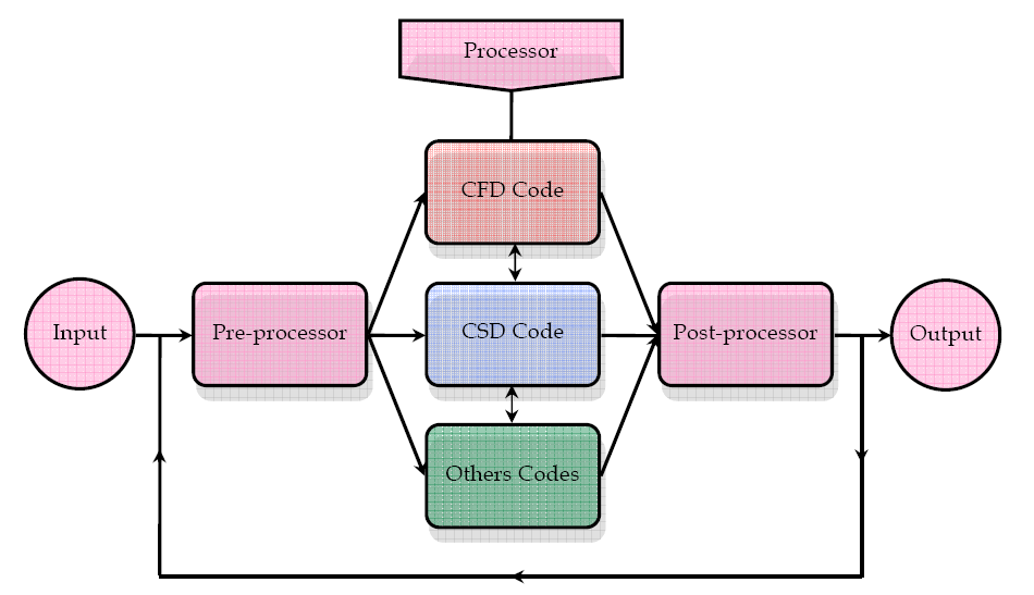
2. FSI method
The FSI problems involve the coupling between the CFD and the CSD codes. This coupling
is used in the partitioned method (Bobovnika et al., 2005 ; Driss et al., 2007 ; Sternel et al., 2008) when the fluid and structural parts are resolved separately. The coupling interface
allows the exchange of the pressures at interface, when the mesh in each fluid and structure field is different and is difficult to place within the same code, hence the utility of the
partitioned algorithm methodology. The coupling interface organizes the transfer of
information and makes an effective coupling between the fluid and the structure fields. At
the fluid-structure interface, the results from the CFD code are applied as a load to the CSD
code. The displacements are calculated using the CSD code to characterize the turbine blade
deformation. To predict numerically the FSI characteristics of the radial turbine, we have
developed a numerical method to simulate the flow depending of the structure
displacements. This method involves three modules: the pre-processor, the processor and
Fluid-Structure Interaction of a Radial Turbine
203
the post-processor. Data is interchanged between these three modules. The implementation
of the computational simulation requires many hypotheses such as the geometrical concept,
the choice of the meshing type, the physical models, the boundary conditions and the
discretization method (Driss et al., 2010).
Fig. 1. Schematic presentation of the FSI method
2.1 Pre-processor
The pre-processor serves as a source of input for the CFD or CSD codes by means of an
operator interface. This is transformed into a suitable form for the processor. The user
activities at the pre-processing stage involve definition of the geometry, mesh generation
and specification of the appropriate boundary conditions. The computational model
requires that the volume occupied by the fluid inside the vessel is described by a
computational grid or cells. In these cells, variables are computed and stored. The
computational grid must fit the contours of the vessel and its internals, even if the
components are geometrically complex. In our CFD applications, a new meshing method is
developed to study the impellers turbines with complex geometries. This method permits
the numerical analyses of turbines with simple and complex geometries (Driss et al., 2005,
2007, 2010). In this method, the computer aided design (CAD) is used at first to construct the turbine shape. After that, a list of nodes is defined to belong to the interface separating the

204
Applied Computational Fluid Dynamics
solid domain from the fluid domain passing through the computational structure dynamics
(CSD) code. Using this list, the mesh in the flow domain is automatically generated for the
three-dimensional simulations. After that, a staggered mesh is used in such a way that four
different control volumes are defined for a given node point, one for each of the three vector components and one for the scalar variable. Therefore, the region to be modeled is
subdivided into a number of control volumes defined on a cylindrical coordinates system.
As application to this method, we are interested to study a stirred tank equipped by a radial turbine (Fig. 2). The tank is a vertical cylindrical vessel with a height-to-diameter ratio H/D
of 1. The shaft is placed concentrically with a diameter ratio s/D of 0.04. The tip to tip
impeller diameter ratio d/D is a 0.5. The turbine has four blades characterised by the length equal to d/2 and the height equal to h. The turbine is placed in a mid-height tank (z=0.5 H).
The geometry system resembles that already studied by Suzukawa et al. (2006) and Nagata
(1975). For the numerical computations, the Young’s modulus and the Poisson’s ratio are
equal to E=2.1 1011 MPa and ν=0.3 respectively. In the following investigations, the fluid is assumed to be incompressible and Newtonian. The structure is assumed to be isotropic
linear and elastic material law is applied.
s
h
H
z
d
D
Fig. 2. Stirred tank equipped with a radial turbine
2.2 Processor
In the processor, the coupling interface is used to allow the transfer of the pressure and the displacement between the CFD and the CSD codes. The pressure provided by the CFD code
Fluid-Structure Interaction of a Radial Turbine
205
is used to calculate the forces applied to the structure. The displacements of the structure are used to update the control volume and the boundary conditions.
2.2.1 CFD code
The CFD code resolves the incompressible Navier-Stokes equations in conjunction with the
standard k-ε turbulence model. The continuity equation is written as follows:
div V 0
f
(1)
The momentum equation is given in the following form:
( V )
f
f div
(2)
V V pI
f
f
f
div R f 2 N r 2 N Vf
t
The standard k-ε turbulence equations are given in the following form:
2
2
k
2 d 1
t
2 d 1
div V
k
1
f
grad k
G
(3)
t
D Re
D Re
k
2
2
2 d 1
t
2 d 1
div V
1
f
grad
C 1
G C 2 (4)
t
D Re
k
D Re
The turbulent kinetic energy production takes the following form:
2
2
2
2
2
2
U
V
U
W
V V
U
W V
U W
G 2
(5)
t
r
r
r
z
r
r
r
r
z
z
r
The k-ε model is based on the concept of turbulent viscosity where k and ε are calculated by solving the equation above. The value of the turbulent viscosity is deduced from the
following equation:
2
2
D
k
C Re
t
(6)
2 d
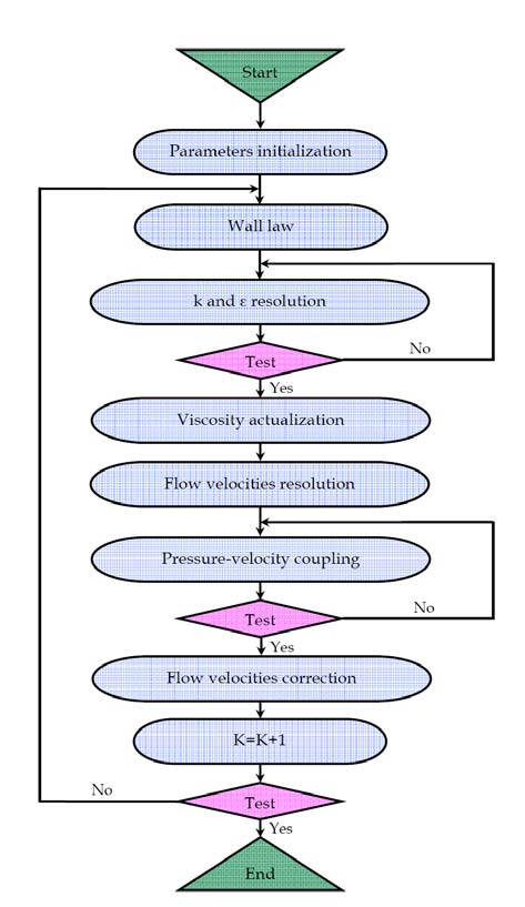
Numerical methods consist on an approximation of the unknown flow variables by means
of simple functions and a discretisation by substitution of the approximation into the
governing flow equations and subsequent mathematical manipulations (Figure 3). The
finite volume method consists on the formal integration of the governing equations of
fluid flow over all the control volumes of the solution domain. The transport equations
are integrated over its own control volume using the hybrid scheme discretization
method. The pressure-velocity coupling is handled by the SIMPLE algorithm of Patankar
(1980). The algebraic equations solutions are obtained in reference to the fundamental
paper published by Douglas and Gunn (1964). The control volume integration,
distinguishes the finite volume method from all other computers techniques. The
resulting statements express the conservation of relevant properties for each finite size
cell.
206
Applied Computational Fluid Dynamics
Fig. 3. Schematic presentation of the CFD code
2.2.2 CSD code
The CSD code allows the static calculation of the structure and solves the partial differential equations of the structure model. In this study, elastic isotropic structures were consid