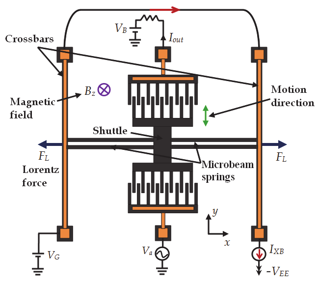
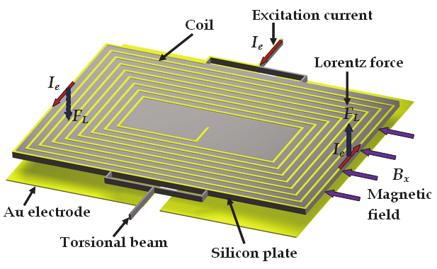
Lorentz force is generated when a sinusoidal current flows into the excitation coil under an
external magnetic field. This force causes an oscillating motion of silicon plate around the
72
Microsensors
Fig. 5. Operation principle of the resonant magnetic field microsensor designed by Bahreyni
& Shafai (2007).
torsional beams. This motion produces a capacitance shift between the Au electrodes and
the silicon plate. A capacitance detection circuit measured the capacitance change that
depends of the magnitude and direction of the external magnetic field. The microsensor
needs a vacuum packaging to increase its performance. For a pressure of 10 Pa and 150 mV
driving voltage amplitude, the microsensor has a resolution of 30 nT, a sensitivity of 0.40
VT-1, a resonant frequency close to 1380 Hz, and a quality factor around 2500. Nevertheless,
it presented a non-linear response from 0 to 3 T.
Fig. 6. Operation principle of the magnetic field microsensor designed by Ren et al. (2009).
Brugger & Paul (2009) developed a novel magnetic field microsensor (dimensions of 7.5
3.2 mm) integrated by an electrostatically driven silicon resonator, an amorphous magnetic
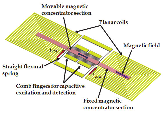
concentrator, and a pair of planar coils. Interdigitated combs (200 14 25 m) are
employed for the electrostatic excitation of the resonator and the capacitive detection of its
resonance (see Fig. 7). The silicon resonator is suspended by four straight flexural springs
(1000 14 25 m). The magnetic concentrator (5000 250 18 m) is constructed using a
Development of Resonant Magnetic Field Microsensors:
Challenges and Future Applications
73
Metglas 2714A ribbon and is cut into three segments separated by two narrow gaps. The
inner segment is attached to the resonator surface and both outer segments are fixed. The
magnetic concentrator saturates to magnetic field above of 713 T. An auxiliary magnetic
field parallel to the magnetic concentrator is generated with the planar coils. Each coil
comprises 12 windings with a linewidth of 55 m and a line-to-line spacing of 15 m. The
resonator is excited at its resonant frequency applying a dc voltage ( Vdc) to it and ac voltage ( Vac) to the half of the interdigitated combs. Its oscillating motion is monitoring using the other half of the interdigitated combs. A magnetic force acts on the resonator when an external
magnetic field parallel to the magnetic-concentrator axis is applied. This force counteracts the
restoring force exerted on the resonator by its four flexural springs, which decrease both the
total spring constant and resonant frequency of the resonator. Then, a quadratic relationship
between the resonant frequency and a magnetic field is obtained. In order to achieve a linear
output signal of the microsensor, the external magnetic field is combined with an auxiliary
magnetic field generated by the planar coils. For a coil current of 80 mA, Vdc = 20V, Vac = 404
mV and a pressure of 10-5 mbar, this microsensor presents a sensitivity of 1.0 MHzT-1, a
resolution of 400 nT, and a quality factor around 2400. It does not need a complex feedback
and modulation electronics; however, it requires a vacuum packaging and a complex
fabrication process. This process combines the following: 1) MEMS technology based on a
silicon-on-insulator (SOI) substrate for the MEM structure; 2) the epoxy-resin-based
attachment of a thin amorphous magnetic ribbon subsequently structured using wet chemical
etching; and 3) micropatterning of the magnetic concentrator by UV-laser.
Fig. 7. Operation principle of a magnetic field microsensor based on a magnetic concentrator
developed by Brugger & Paul (2009).
Generally, a resonant magnetic field microsensor with capacitive detection needs a vacuum
packaging in order to increase its sensitivity and resolution. It suffers from parasitic
capacitances, which can be reduced through the monolithic integration of the
micromachined resonators with electronic circuits.
2.3 Optical sensing
This section includes the resonant magnetic field microsensors based on MEMS that use
optical sensing.
74
Microsensors
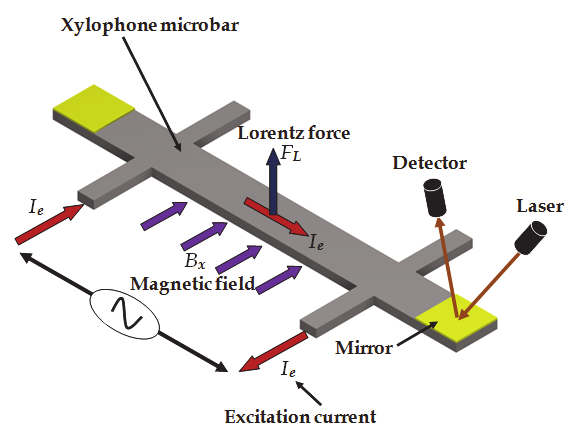
Zanetti et al. (1998) fabricated a magnetic field microsensor formed by a xylophone
microbar, which is supported (at the nodes of its fundamental vibration mode) by four
microbeams. The microsensor uses optical detection for measuring the deflections of the
xylophone microbar under an external magnetic field parallel to its length, as shown in Fig.
8. The interaction of this field with ac excitation current ( I) flowing into the microbar
produces a Lorentz force that deflects the microbar. If the ac excitation current is supplied
with one frequency equal to the bending resonant frequency of the microbar, then, its
deflection is increased. This deflection depends of the magnitude of the external magnetic
field and is measured using a miniature laser and a position sensitive detector. Thus, the
magnetic signal is proportional to the deflections of the xylophone microbar. The
microsensor has dimensions of 5000 500 250 m, a quality factor close to 700, a resolution
around 1 nT and a power consumption of few milliwatts.
Fig. 8. Operation principle of a magnetic field microsensor with optical detection based on a
xylophone microbar designed by Zanetti et al. (1998).
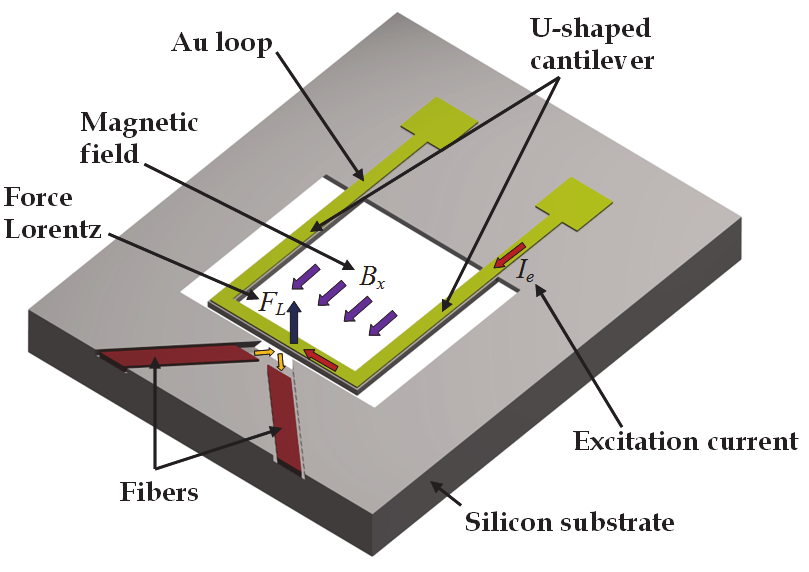
Keplinger et al. (2003, 2004) proposed a resonant magnetic field microsensor based on a
micromachined U-shaped silicon cantilever and an optical sensing system. The cantilever
(1100 100 10 m) contains on its surface a 0.5-m-thick Au layer, which flows an ac
excitation current. A Lorentz force is generated due to the interaction of the current with a
magnetic field parallel to the length of the U-shaped cantilever. This force causes a bending
motion of the cantilever that is measured through optical fibers. Thus, the magnetic input
signal is converted into a movement of the cantilever, which is increased when the
cantilever operates at its resonant frequency. The optical sensing uses two-fiber
arrangements for avoiding the problem of the interfering reflected light. In the first design
the emitted light beam is reflected only once at the cantilever front side, as shown in Fig. 9.
Nevertheless, it requires a large lateral space for the chip and microsensor. The second
design considers a cracked cantilever to allow a parallel alignment of the fibers (see Fig. 10),
which requires a perfect vertical front side of the cantilevers. This optical detection system
allows the efficient transmission of the microsensor signal in an electromagnetically noisy
environment. This microsensor detects magnetic fields from 10 mT to 50 T and has a
resonant frequency close to 5 kHz, a quality factor of 200 at atmospheric pressure, a
resolution of 10 mT, and a power consumption of a few milliwatts.
Development of Resonant Magnetic Field Microsensors:
Challenges and Future Applications
75
Fig. 9. Operation principle of a resonant magnetic field microsensor integrated by a U-
shaped silicon cantilever and two fibers placed in curved channels, which was developed by
Keplinger et al. (2003, 2004).
Fig. 10. Operation principle of a resonant magnetic field microsensor integrated by a U-
shaped cracked cantilever and two parallel fibers, which was developed by Keplinger et al.
(2003, 2004).
Wickenden et al. (2003) reported a resonant magnetic field microsensor formed by a
polysilicon xylophone microbar (500 50 2 m), which has a similar performance to
microsensor designed by Zanetti et al. (1998). A magnetic input signal is converted into an
oscillating motion of the xylophone microbar. This motion is detected by an optical readout
system based on a laser diode beam and a position sensitive detector. This microsensor has a
resonant frequency of 78.15 kHz, a quality factor around 7000 at 4.7 Pa, ac current of 22 A,
a thermal noise of 100 pTAHz-1/2, and a resolution on the order of nanoteslas. However, it
presents a linear response up to 150 T and its performance is affected by variations of
pressure and temperature. The optical readout system used in resonant magnetic field
microsensors allows a reduction in their electronic circuitry and weight. Furthermore, the
microsensors with optical sensing have immunity to EMI.
76
Microsensors
2.4 Piezoresistive sensing
This section includes the description of several resonant magnetic field microsensors with
piezoresistive sensing.
Beroulle et al. (2003) reported a magnetic field microsensor integrated by a resonant U-
shaped cantilever (520 m length and 80 m thick), a planar aluminium coil of 8 turns, and a
Wheatstone bridge of polysilicon strain gauges. This microsensor exploits the Lorentz force
principle in order to measure an external magnetic field, converting it into an electrical
output signal through Wheatstone bridge. The microsensor was fabricated using an
industrial CMOS processes with a post-processing etch step to release its resonant structure.
It has a sensitivity of 0.53 VT-1, a theoretical resolution of 2 T, a thermal noise of 5.3 nVHz-
1/2, a resonant frequency of 8.97 kHz, a quality factor of 59, and a mass of 750 ng.
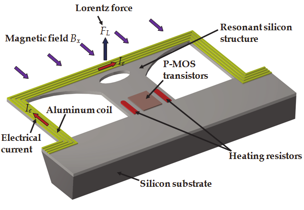
Sunier et al. (2006) developed a magnetic field microsensor using a resonant silicon structure, a
planar aluminium coil, two heating resistors, and P-channel Metal Oxide Semiconductor
(PMOS) transistors (see Fig. 11). This microsensor operates based on Lorentz force principle
and provides a frequency output signal. The silicon structure vibrates at its resonant frequency
because of the thermal actuation of two heating resistors. The oscillating motion of the silicon
structure is detected using PMOS transistors connected in a Wheatstone bridge. A Lorentz
force (generated by the interaction between an electrical current flowing through coil and an
external magnetic field) changes the total spring constant of the resonant structure. This
modifies the resonant frequency value of the silicon structure. Thus, the resonant frequency
shift is related to the magnitude of the external magnetic field. This microsensor has an
efficient continuous offset cancelation, high robustness, and low cross sensitivity. In addition,
it presents a sensitivity of 60 HzT-1, a resolution of 1 T, a resonant frequency of 175 kHz, a
quality factor of 600, and a power consumption close to 5 mW.
Fig. 11. Operation principle of a resonant magnetic field microsensor with frequency output
designed by Sunier et al. (2006).
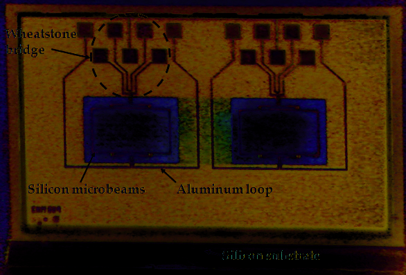
Herrera-May et al. (2009b) developed a resonant magnetic field microsensor with
piezoresistive sensing, which contains a resonant silicon microplate (400 150 15 m)
supported by four bending microbeams, an aluminium loop, and a Wheatstone bridge of
four p-type piezoresistors (see Fig. 12). It exploits the Lorentz force for monitoring external
magnetic fields. This force causes an oscillating motion of the microplate and microbeams
that strains two piezoresistors. This changes the piezoresistors resistance, modifying the

Development of Resonant Magnetic Field Microsensors:
Challenges and Future Applications
77
output voltage of the Wheatstone bridge. Then, the magnetic input signal is converted into an
electrical signal. This microsensor was designed for Tenaris TAMSA Corporation for
measuring residual magnetic fields in welded steel tubes. It was fabricated using the bulk
micromachining technology of the Microelectronics Institute of Barcelona (IMB-CNM, CSIC).
Its characteristics are: sensitivity of 0.403 VT-1, resolution of 143 nT, resonant frequency of
136.52 kHz, quality factor of 842, and a power consumption below 10 mW. However, this
microsensor presents a offset and a nonlinear response for low magnetic fields.
Fig. 12. SEM image of a die with two resonant magnetic field microsensors with
piezoresistive sensing designed by Herrera-May et al. (2009b).
The MEMS group (Herrera-May et al., 2011) from MICRONA-UV into collaboration with
IMB-CNM developed a resonant magnetic field microsensor integrated by a rectangular
loop (700 450 5 m) of silicon beams suspended with four bending beams (130 12 5
m), an aluminium loop (1 m thick), and four p-type piezoresistors connected into a
Wheatstone bridge (see Fig. 13). This microsensor operates based on Lorentz force and has a
linear response under weak magnetic fields from 40 to 2000 T. In addition, it has sensitivity
4.8 times larger than the microsensor reported by Herrera-May et al. (2009b). This
microsensor presents a resolution close to 43 nT, a resonant frequency of 22.99 kHz, a
quality factor of 96.6 at atmospheric pressure, and a low power consumption of 16 mW.
Later, researchers of MICRONA-UV designed other resonant magnetic field microsensor
with piezoresistive sensing (see Fig. 14). It was used for monitoring magnetic fields generate
by an electronic neuron developed by researchers from Institute of Physiology-BUAP (Tapia
et al., 2011). This microsensor exploits the Lorentz force and is formed by an arrangement of
silicon microbeams (700 450 5 m) suspended by four bending microbeams, an
aluminium loop (1 m thick), and a Wheatstone bridge with four p-type piezoresistors. It
has a compact structure, a response linear to low magnetic fields, a sensitivity of 1.2 VT-1, a
resolution of 80 nT, a resonant frequency of 13.87 kHz, a quality factor of 93 at atmospheric
pressure, a power consumption of 2.05 mW, and a simple signal processing.

78
Microsensors
Fig. 13. Microphotograph of a die with two resonant magnetic field microsensors designed
by the MEMS group of MICRONA-UV.
Fig. 14. SEM image of a die with two resonant magnetic field microsensors with
piezoresistive detection used for neural applications (Tapia et al., 2011).
A piezoresistive sensing system used into magnetic field microsensors can allow them a
simple signal processing, high sensitivity, and low-cost fabrication. Nevertheless, it is
affected by temperature variations, which can be reduced through compensation circuits.
2.5 Comparison of resonant magnetic field microsensors
Most the resonant magnetic field microsensors have a compact structure, small size, and
high sensitivity, wide dynamic range, and easy signal processing. Several of them can
Development of Resonant Magnetic Field Microsensors:
Challenges and Future Applications
79
measure low magnetic fields around nanoteslas with low consumption power. Their
dynamic range can be adjusted changing the magnitude of the excitation current, allowing
them to measure lower or higher magnetic fields. A comparison of the main characteristics
of these microsensors are indicates in Table 1. They could compete with conventional
magnetic sensors for monitoring magnetic fields with resolution on the order of nanoteslas.
Size of
Sensing
Resolution Resonant
Quality
resonant
Microsensor
technique
(nT)
frequency
factor
structure
(kHz)
(m × m)
Kádár et al. (1998)
Capacitive
1
2.40
700 @ 5 Pa
2,800 × 1,400
Emmerich &
Capacitive
Schöfthaler (2000)
200
1.30
30 @ 101 Pa
1,300 × 500
Tucker et al. (2002)
Capacitive <103 100
1000 @ 1 Patm <1,000 × 1,000
Bahreyni et al. (2007)
Capacitive 217 27
15000 @ 2 Pa
520 × 400
Ren et al. (2009)
Capacitive
30
1.38
2500 @ 10 Pa
3000 × 2000
Brugger & Paul (2009) Capacitive
400
2.5
2400 @ 10-5 Pa 7500 × 3200
Zanetti et al. (1998)
Optical 1 --- *
7000 @ Patm
5,000 × 500
Keplinger et al. (2003,
Optical 107
5
200 @ P
2004)
atm
1,100 × 1,000
Wickenden et al. (2003)
Optical
<103
78.15
7000 @ 4.7 Pa
500 × 50
Beroulle et al. (2003) Piezoresistive
2 × 10³
8.97
59 @ Patm
520 × 520
Sunier et al. (2006) Piezoresistive
103
175
600 @ Patm
400 × 185
Herrera-May et al. Piezoresistive
143
136.52
842 @ P
(2009b)
atm
400 × 150
Herrera-May et al. Piezoresistive
43
22.99
96.6 @ P
(2011)
atm
700 × 450
* Data not available in the literature
Table 1. Main characteristics of resonant magnetic field microsensors.
3. Challenges and future applications
This section considers some challenges and potential applications of the resonant magnetic
field microsensors.
Future commercial markets will require the development of multifunctional sensors on a
single chip for monitoring several input signals such as magnetic field, pressure,
acceleration, and temperature. These sensors will be integrated by several microstructures,
transducers, and electronic circuits on a same substrate using monolithic fabrication. They
will have important advantages such as small size, compact structure, low power
consumption, and high functionality. Therefore, the integration on a single chip of the
resonant magnetic field microsensors with other type of sensors is an important challenge.
Another challenge is the suppression of any background noise in order to increase the
magnetic resolution. The performance of the future magnetic field microsensors will be limited
by the variations in Earth’s magnetic field because of geological effects. In addition, the
reduction of the output response offset and the temperature dependence of future
microsensors are needed. Potential applications into the automotive industry,
telecommunications, and consumer electronics products demand magnetic field microsensors
80
Microsensors
of low cost and high reliability. Also, a challenge is the optimization of their performance and
the decrease of the design-phase time. Investigations on new materials with better electrical
and mechanical properties than silicon could be used into the future microsensors.
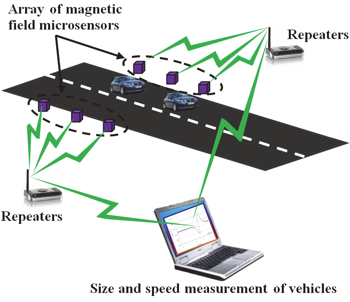
Automotive industry could be a future market of the magnetic field microsensors in order to
detect the speed and size of vehicles (see Fig. 15). A traffic’s detection system may be formed
by two microsensors (separated by 1 meter distance from each other) placed in parallel
beside the road. The microsensors will measure the change of the Earth’s magnetic field due
to the vehicle motion, which will be proceeded to A/D converter and digital data processing
system. The magnetic variation will depend of the vehicle’s size and speed, and it will be
detected by the microsensors in different times ( t1 and t2). Then, the vehicle’s speed will be determined through the ratio of the separation distance between the two microsensors to the
time difference t1- t2. This system could be applied with an intelligent signal control to decrease traffic congestion on roads.
Fig. 15. Schematic diagram of a traffic’s detection system based on magnetic field
microsensors.
Also, magnetic field microsensors could be employed at the electronic stability program
(EPS), which keeps the vehicle dynamically stable in critical situations such as hard braking
and slippery surfaces. ESP systems needs data about steering-wheel angle, lateral
accelerations, yaw rate, and wheel speed. These parameters could be measured through
accelerations, gyroscopes, pressure sensors, and magnetic field microsensors.
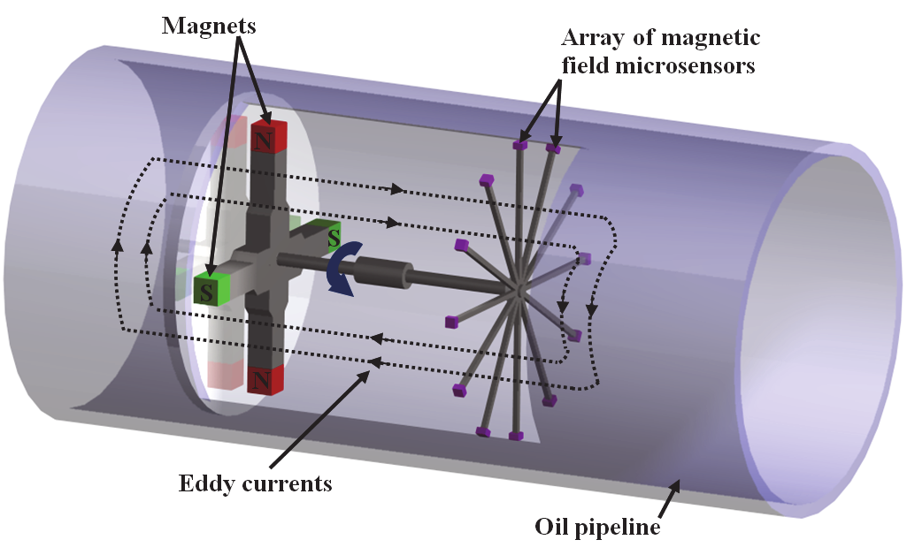
Another potential application of the magnetic field microsensors is the monitoring of the
corrosion and geometrical defects in ferromagnetic pipeline. Fig. 16 depicts an inspection
platform for oil pipeline walls reported by Nestleroth & Davis (2007). It is integrated by a
rotating permanent magnetic exciter, which may induce uniform eddy currents in the pipe
wall. The eddy currents are deflected pipeline defects such as corrosion and axially sligned
cracks. The variation of the current densities (that causes a magnetic flux leakage in the pipe
wall) could be measured by magnetic field microsensors. Therefore, the defects location
could be reached with these microsensors.
Development of Resonant Magnetic Field Microsensors:
Challenges and Future Applications
81
Fig. 16. Schematic view of an inspection platform of oil pipeline walls that consists of a
rotating permanent magnetic exciter and an array of magnetic field microsensors.
Magnetic field microsensors could detect cracks, geometrical defects or stress concentration
zones in ferromagnetic structures using passive magnetic techniques such as Metal
Magnetic Memory (MMM). This technique relies on the self magnetization of ferromagnetic
structures by ambient magnetic fields such as the Earth’s field (Wilson et al., 2007). It
measures changes in the self magnetic leakage field of the ferromagnetic structures due to
geometrical discontinuities and high density dislocations.
New cell phones could use resonant magnetic field microsensors, accelerometers, and
gyroscopes integrated on a single chip for their global positioning system (GPS). This could
reduce the size, cost, and power consumption of the cell phones.
The important advantages of resonant magnetic field microsensors will allow their
incorporation in future commercial markets, principally into the automotive sector,
telecommunications, and consumer electronics products.
4. Conclusion
The development of resonant magnetic field microsensors based on MEMS has been
presented. These microsensors exploit the Lorentz force for measuring magnetic fields and
can use different sensing types such as: capacitive, optical, or piezoresistive. Their main
advantages are small size, com