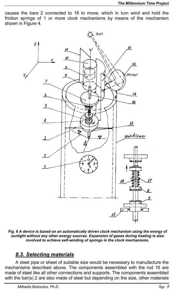
The operation principle of this device is based on an automatically driven clock mechanism using the energy of sunlight without any other energy sources. Expansion of gases during heating is also involved to achieve self-winding of springs in the clock mechanisms [10].
8.2.1. ArrangementA rod 10 with a piston 9 having sufficient diameter is mounted by means of the stand 11 on a clock tower or building. The piston can move freely with a little clearance (but should be tight in the cylinder) along a cylinder 8 with a bottom and airtight. Mounted on the bottom is a threaded rod 16. Installed on this thread, which is a large-pitch one, are two couplings having face V-shaped teeth (a butt joint) 6 and inner thread like for 16. Another tooth coupling 5 is located at a distance from 6, which is coaxially mounted on the rod 16 and connected to two discs 4 and 7. A shield 12 is attached to the two discs 4 and 7 by means of stands. The shield 12 is a semi-cylinder having a diameter larger than 8. The shield 12 along with the stands and the disc 4 (7) can rotate on a bearing in a housing 15. The housing 15 is fixed to the walls of the tower (building) by means of horizontal joints. Located at a suitable place facing the cylinder 8 is a reflective parabolic mirror 13 so sunbeams can be focused on the cylinder 8. The bottom end of the rod 16 is hinged to bar(s) 2 via which it is connected to the drum of the spring of the clock 1 using the connection shown on Figure 4 (by means of a gear rack, eccentric and ratchet clutch). One partition spacer 17 and two spiral springs 18 are located between the tooth couplings 6.
8.2.2. OperationThe warm air (or some special gas highly expanding when heated) in the cylinder 8 is periodically heated and cooled down by sunbeams focused on the cylinder by means of the parabolic mirror 13 or a reflector. The expansion of the gas causes the cylinder 8 to move down until the butt tooth coupling 6 engages with the tooth coupling 5 and thus rotates by means of the large-pitch thread the spacer 4 and the shield 12 at 180°. This causes the shield to rotate and obstruct the beams reflected by 13 so they cannot fall on the cylinder 8. As a result of this the cylinder 8 and the gas it contains cool down and the cylinder moves up by atmospheric pressure. This vertical movement of the cylinder 8 with the rod 16
could also be used like aluminium or copper alloys, PVC, etc. Suitable seals shall be needed for the manufacture of the cylinder 8 and the piston 9 which are available in pneumatics.