Miltiadis Boboulos, Ph.D. Page 48
17.2.2. Operation
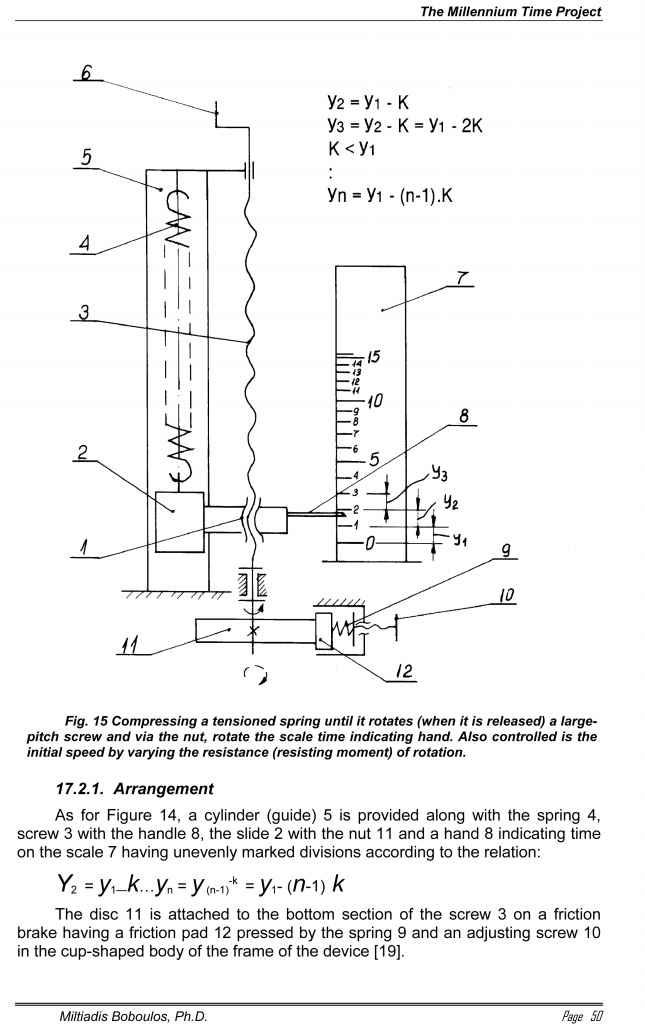
When the spring 4 is released it pulls the slide 2 rotating the screw 3 around its axis via the nut 1 and rotating 11. Controlling the pressure of 12 against the disc 11 by means of the screw 10 and the spring 9 controls the initial rotation speed at start-up. The hand 8 indicates the time on the uneven scale 7 and the handle 6 is used to re-load.