The Input Console window is the main DSP Factory window. If you view the DSP Factory as an external digital mixer, feeding and receiving audio signals to and from VST, this window is the mixer panel.
P Static initial settings in the DSP Factory windows are saved with the Song. You can also automate your mixer actions, as described on page 36.For each DS channel, there is a large number of controls and settings. Showing them all at the same time would require an impossibly large window. Therefore, each channel strip in the Input Console is divided into two “halves”, the Upper and Lower display. You can select what should be shown on these two displays, independently for each channel:
The Lower Display
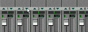 2. Point at the small triangle pointing downward, and press the mouse button.
A pop-up menu appears with the three modes for the Lower display.
2. Point at the small triangle pointing downward, and press the mouse button.
A pop-up menu appears with the three modes for the Lower display.
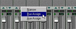
3. Select one of the display modes.
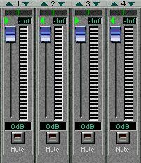
If you select the “Narrow” mode, the channel strip will be as narrow as possible to conserve screen space, showing only the basic level and pan controls (see below). The controls in the other modes are described on page 15.
The Upper Display
1. Locate the dividing line between the Upper and Lower display for the channel strip.
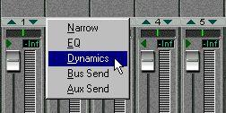
3. Select one of the display modes.
If you select the “Narrow” mode, the channel strip will be as narrow as possible to conserve screen space, with no controls in the Upper display (see below). The controls in the other modes are described on page 17.
The selection of display modes is independent for the Upper and Lower displays, with one exception:
• Selecting the “Narrow” mode for the Upper or Lower display will automatically select the “Narrow” mode for the other display as well.
Since the width of the whole channel strip is minimized, there is then no room for any additional controls in either display.
 Input Selector Stereo Mix on/off switch
 The Lower Display in “Bus Assign”, “Aux Assign” and “Narrow” modes. Control
Pan Control
Fader Setting Channel Solo Channel Mute Input Selector
ExplanationSets the stereo position of the channel. This is used when you are assigning channels to the stereo master out or to the buses (when the Bus Sends are in “Post Pan” mode - see below).
When this is activated (when the green arrow is lit), the two channels in an odd-even pair are linked. This means that if you move a control for one of the channels, the other channel will be affected in the same way. Pan is not affected by the Stereo link.
• You can also momentarily “stereo-link” unlinked faders and other controls by holding down [Alt] while moving the controls. Conversely, for channel pairs with Stereo link activated, holding down [Alt] allows you to adjust settings separately for each channel in the pair.
Determines the level of the channel, both when playing back and when recording signals into VST.Indicates the current fader setting in dB.
Mutes all other channels.
Turns off the sound of the channel.
This display indicates the currently selected input source for the channel. Clicking on it brings down a pop-up menu, from which you can select another input source.
ControlThis switch determines whether the channel is connected to the Stereo Mix (the master fader to the right on the Input Console panel) or not. You may want to deactivate this for channels which you have routed to separate outputs, using the Bus or Aux Sends. The switch is duplicated in the Bus Send panel in the Upper display.
Use these to turn the Aux sends on or off for the channel. These buttons are “mirrored” in the Aux Send panel in the Upper display.About the FX Return Channels
The channels labeled “1” - “4” to the right in the Input Console window, are by default used as stereo effect returns for the on-board effect units. FX Return channels 1 and 2 control the return level from FX Unit 1, and FX Return channels 3 and 4 control the return level from FX Unit 2. The FX Return channels differ from the regular channels in the following ways:
• There are no Solo buttons for the FX Return channels.
• The two channel pairs (1-2 and 3-4) are stereo linked by default.
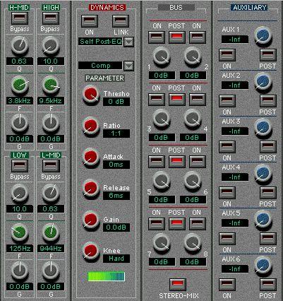 The Upper display in “EQ”, “Dynamics”, “Bus Send” and “Aux Send” modes.
EQ Mode
When EQ Mode is selected for the Upper Display, you have access to a four band parametric equalizer. Each EQ band has the following parameters: Bypass A Bypass-switch for the band. When the Bypass-indicator is lit, the EQ band is disabled. Q The Q value for the EQ band, ranging from10 (narrow) to 0.1 (wide) in 41 steps. Also used to select LPF/HPF or Shelving modes for the Low and High EQ bands (see below). F The center frequency of the EQ band, from 21 Hz to 20 kHz in 120 steps. G The boost or cut (± 18 dB in steps of 0.5 dB).
Normally, all four EQ bands are of the regular full parametric type, but you can switch the High and Low bands to Shelving or High/Low Pass Filter mode:
• To select High/Low Shelving mode for the High or Low EQ band, turn the Q knob fully to the right.
• To select High/Low Pass Filter mode for the High or Low EQ band, turn the Q knob fully to the left.
This converts the High EQ band to a Low Pass Filter and the Low EQ band to a High Pass Filter. In this mode, the Gain (G) setting is disabled.
When Dynamics Mode is selected for the Upper Display, you have access to a complete multi-mode Dynamics processor for the channel. You use the Type pop-up menu (right above the “Parameters” label) to select which type of dynamics processing to use:
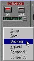
Type
Comp
Gate
Ducking
Description
A compressor, attenuating signals above a specified threshold level. Mutes signals below a specified threshold level.
Attenuates the signal when the level exceeds a specified threshold. Normally, the signal used for level detection (the Key In signal - see below) is another than the processed signal. For example, a common use for ducking would be voice-overs, when the background music level should be reduced each time the announcer speaks.
An expander, attenuating signals below a specified threshold level, thus reducing low-level noise and effectively increasing the dynamic range.A combination of compressor, expander and limiter: The compressor compresses signals that exceed a specified threshold level, while the expander attenuates signals below a level determined by the threshold level and the Width setting. The limiter prevents the signal from exceeding 0 dB.
The two compander types (H and S, for Hard and Soft) have different expansion ratios; CompandH will attenuate low level signals more drastically than CompandS.
Key-In pop-up menu
 On button Link button
In pop-up menu Click this to activate the Dynamics processor for the channel.
When this is activated, the dynamics processing is linked for the two channels in an odd-even pair. This means that a mix of the two channels is used to “trigger” the dynamics processor. Use this mode for stereo channel pairs, to maintain the stereo balance.
Determines which signal should be used to “trigger” the dynamics processing: Self Post-EQ: The channel signal, post-EQ
Self Pre-EQ: The channel signal, pre-EQ
Aux 1: The total signal on the Aux 1 bus
Aux 2: The total signal on the Aux 2 bus
Left Post-EQ: The signal of the left channel in a pair, post-EQ
Left Pre-EQ: The signal of the left channel in a pair, pre-EQ
(“Left” options are only available for even-numbered channels)
This pop-up menu is only available when Link mode is activated. Use this to determine which signal(s) the dynamics processor should affect; L (left channel in the pair), R (right channel in the pair) or Both.
In the lower half of the Dynamics panel, you will find the actual controls: Parameter ThresholdDetermines the threshold level at which the dynamics processor is “triggered”. Whether signal levels above or below this level will trigger the processing, depends on the selected dynamics type.
(Comp, Expander and Compander types only.) Determines the amount of compression/expansion. For the Compander types, this determines the compression, while the expansion ratio is fixed.
This determines how soon the signal is affected (compressed, gated, expanded, etc) once the dynamics processor has been triggered.(Comp, Expander and Compander types only.) Determines how soon the dynamics processor returns to normal gain once the signal level goes back below/above the threshold level.
(Comp, Expander and Compander types only.) Sets the output signal level. Use this to compensate for overall level changes caused by the dynamics processing.
(Comp and Expander types only.) Determines how compression/expansion is applied at the threshold point. “Hard knee” means that the specified compression/expansion ratio is applied as soon as the threshold level is reached, while the five “Soft knee” settings apply the compression/expansion gradually for a more natural sound.
(Gate and Ducking types only.) Determines the amount of attenuation when the processing is triggered, with lower values resulting in more attenuation. If you want the Gate/Ducker to mute the signal completely when triggered, set this parameter to its lowest value (-70 dB).
(Gate and Ducking types only.) Determines how long the gate stays open (or how long the ducking effect remains active) once the trigger signal has fallen below the threshold level.
(Gate and Ducking types only). Determines how fast the gate is closed (or, with Ducking, how fast the gain returns to normal) after the Hold time.(Compander types only.) This determines how far below the threshold level expansion is applied to the signal. If the Threshold level is -10 dB and the Width is set to 20 dB, expansion will be applied to signals with levels below -30 dB (20 dB below threshold).
This meter indicates the dynamic gain reduction.Bus Send Mode
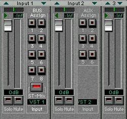
P The Bus Sends are always post-fader. This means that in many cases (e.g. when using the buses for recording into VST) there is no need to adjust the individual bus send levels – you only need to activate the desired buses in the Lower display (Bus Assign mode) and set the recording level using the faders. This assumes that you keep all bus send level knobs at their maximum setting.
In this mode you can view and control the eight Bus Sends for the channel. For each bus there is an on/off button (mirrored in the Lower display in Bus Assign mode) and a level control. For each pair of Bus Sends (1-2, 3-4, etc), there is also a Post Pan switch:
• When the Post Pan switch is activated for a Bus Send pair, the Pan control for a channel is used to pan the signal between the two buses in the pair.
Panning a signal fully left will send it to the odd-numbered bus only and vice versa. When Post Pan is activated, the Bus on/off buttons are linked for each pair, so that activating or deactivating a Bus Send (in this panel or in the Lower display) automatically activates/deactivates the other Bus Send in the pair. This is useful when you are recording in stereo, or when you have assigned the buses to separate outputs for stereo monitoring, etc.
• When the Post Pan switch is deactivated for a Bus Send pair, the channel signal is sent to each activated bus regardless of the Pan setting.
This may be preferable when you are recording in mono, since it allows you to route a DS channel to a VST input without having to take the Pan setting into account.
Below the Bus Sends you will find a Stereo Mix on/off button, which determines whether the channel should be sent to the main Stereo Mix or not. This button is duplicated in the Bus Assign panel in the Lower display.
Aux Send ModeIn this mode you can view and control the six Aux Sends for the channel. For each send there is a level control with a numeric display showing the current setting, an on/off switch (mirrored in the Lower display in Aux Assign mode) and a Post-fader switch.
P Aux Sends 5 and 6 are “hard-wired” to the on-board effect units (FX Unit 1 and FX Unit 2). To avoid feedback, Aux Sends 5 and 6 are disabled for the FX Return channels.P If you have two DS2416 cards installed, you can address all four effect units by using Aux Sends 3-6.
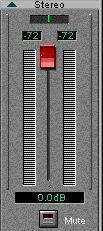 To the right in the Input Console window you will find the Stereo Mix section. This differs slightly from the regular channel strips:
Lower Display
In the Stereo Mix section, there are no different modes for the Lower display. It always contains a stereo master fader with a numerical display, stereo level meters and numeric level indicators, a balance control and a Mute button, for silencing the Stereo Mix output totally. The Mute button does not affect the buses or Aux sends.
Upper DisplayThere are two modes for the Stereo Mix Section Upper display: EQ and Dynamics. These both feature the same controls as in the regular channel strips.
 Control
This works just like the Read and Write buttons in the VST Channel Mixer. To create an automated mix, you click Write and perform the desired mixing maneuvers, during playback or in Stop mode. To play your recorded mixer actions back, activate the Play button and start playback.
For more details about automation, see page 36.
Determines which signal the level meters should show: When the button is activated, the meters will show the levels postfader. When it isn’t activated the meters will show the input levels, regardless of fader positions (which is useful when checking input levels from external sound sources).
When this is activated, the level meters will drop more slowly, making it more easy to discern quick level changes. This switch will also affect the meters in the Bus/Aux Console (see page 24).
When this is activated, the numeric level indicator will keep the highest value displayed, making it easy to spot maximum levels. To reset the indicator in Peak Hold mode, click twice on the Peak Hold button.
This switch will also affect the numerical level indicators in the Bus/Aux Console (see page 24)