In this chapter, we focus mainly on the non-invasive approaches for BCI. Several techniques
b. Decoding algorithm: It translates the signal features into device
have been proposed to measure relevant features from EEG or MRI signals and to decode
commands that accomplish the user’s request.
the brain targets from those features. Such techniques are reviewed in the chapter with a
focus on a specific approach. The basic idea is to make the comparison between a BCI
3. Output device: In general, the output device may be prosthesis with its control
system and the use of brain imaging in medical applications. Actually, based on neural
system or a video screen. The output is the feedback the brain uses to maintain and
signals like EEG, the electro-magnetic activity at the surface of the cortex may be measured.
improve communication or to control prosthesis.
A practitioner would make use of such images of the cortex surface to detect abnormalities
or diseases. The chapter shows this parallelism and how it has been exploited to build a
4. Operating format: It guides the operation (onset, offset, and timing) of the BCI.
state of the art BCI system.
After a brief description of a general BCI system, a brief review of the neural signals and
their measurements is provided. A particular focus is on EEG signals. EEG is a standard
Signal acquisition
Mechanical
and preprocessing
Feature
Decoding
arm control
non-invasive and nearly risk-free method that has been extensively used in medical
Extraction
applications. In order to decode the signals collected, feature extraction is first performed.
Algorithm
Based on the relevant features computed, a classification is performed. State of the art
feature extraction approaches systems are presented in the chapter. Brain imaging
techniques allow to visualize the surface of the cortex. This suggests using brain imaging
techniques to evaluate the electro-magnetic activity at the cortex surface that will define a
vector of features. These features will be given to the decoding/classification algorithm as
input. At the output of the classification algorithm, the decoded intention would be
Adjust
detected. The chapter presents briefly several techniques for brain imaging with a focus on
parameters
subspace correlation methods. These methods are detailed in the chapter.
Several classifiers, e.g. Artificial Neural Networks (ANN), Independent Component
Fig. 1. Basic design and operation of a Brain-Computer Interface (BCI).
Analysis (ICA) and other approaches have been used extensively in BCI systems. As an


Brain Imaging and Machine Learning for Brain-Computer Interface
59
first two blocks are critical for the success of the BCI. Actually, the neural signals to be
example both the Support Vector Machine (SVM) and the Gaussian Mixture Model (GMM)
measured have to be chosen adequately and the decoding of these signals should be
are presented.
accurate. The use of the output of the decoder in the third block of a BCI application is a
pure engineering problem. This block should take into account some specific aspects related
To illustrate the concepts presented, a BCI system is described and some experimental
to the errors that a BCI system may lead to and the particular context of a BCI. This chapter
results are provided. The system makes use of signal subspace decomposition as feature
focuses on the first two blocks, i.e. the acquisition and decoding of neural signals.
extraction and support vector machine as classifier. The chapter provides some hints about
the system implementation before providing conclusions and perspectives.
Informative neural signals may be collected at the microscopic level (e.g. spike trains),
mesoscopic level (e.g. electrocorticogram) and/or, macroscopic level (e.g.
electroencephalogram). In order to collect the spike trains, electrodes are generally
2. BCI System
implanted in a surgery with non negligible risk. BCI approaches based on these signals are
The basic design and operation of a BCI system include the following components (Veltink
invasive approaches. Besides the high surgical risks, such approaches have to face other
et al., 2001)(Wolpaw et al., 2002)(Ebrahimi et al., 2003):
challenges. The power consumption is a key issue limiting the possibility of advanced
processing in the electrode implantation area. Therefore, neural signals have to be
1. Signal acquisition and digitization: The input is the EEG activity or brain signals
transmitted out of the implantation area which by itself is also a challenge.
from the user. This input is acquired by recording electrodes, amplified, and
digitized. As stated above the signal acquisition defers largely from invasive and
Clearly, non-invasive approaches, e.g. EEG signals-based systems, are more attractive than
noninvasive approaches.
the invasive ones for the limited risk they may incur. However, signals in non invasive
approaches are less precise than the spike trains measured in electrode-based approaches.
2. Signal processing: It comprises two stages:
Advanced processing is therefore required in the decoding block.
a. Feature extraction: Features related to specific electrophysiology
components are extracted.
In this chapter, we focus mainly on the non-invasive approaches for BCI. Several techniques
b. Decoding algorithm: It translates the signal features into device
have been proposed to measure relevant features from EEG or MRI signals and to decode
commands that accomplish the user’s request.
the brain targets from those features. Such techniques are reviewed in the chapter with a
focus on a specific approach. The basic idea is to make the comparison between a BCI
3. Output device: In general, the output device may be prosthesis with its control
system and the use of brain imaging in medical applications. Actually, based on neural
system or a video screen. The output is the feedback the brain uses to maintain and
signals like EEG, the electro-magnetic activity at the surface of the cortex may be measured.
improve communication or to control prosthesis.
A practitioner would make use of such images of the cortex surface to detect abnormalities
or diseases. The chapter shows this parallelism and how it has been exploited to build a
4. Operating format: It guides the operation (onset, offset, and timing) of the BCI.
state of the art BCI system.
After a brief description of a general BCI system, a brief review of the neural signals and
their measurements is provided. A particular focus is on EEG signals. EEG is a standard
Signal acquisition
Mechanical
and preprocessing
Feature
Decoding
arm control
non-invasive and nearly risk-free method that has been extensively used in medical
Extraction
applications. In order to decode the signals collected, feature extraction is first performed.
Algorithm
Based on the relevant features computed, a classification is performed. State of the art
feature extraction approaches systems are presented in the chapter. Brain imaging
techniques allow to visualize the surface of the cortex. This suggests using brain imaging
techniques to evaluate the electro-magnetic activity at the cortex surface that will define a
vector of features. These features will be given to the decoding/classification algorithm as
input. At the output of the classification algorithm, the decoded intention would be
Adjust
detected. The chapter presents briefly several techniques for brain imaging with a focus on
parameters
subspace correlation methods. These methods are detailed in the chapter.
Several classifiers, e.g. Artificial Neural Networks (ANN), Independent Component
Fig. 1. Basic design and operation of a Brain-Computer Interface (BCI).
Analysis (ICA) and other approaches have been used extensively in BCI systems. As an
60
Biomedical Imaging
3. Feature Extraction
Several measurement procedures have been used in modern BCI. As stated earlier, they can
be divided into two categories. Non invasive procedures include Electroencephalography
(EEG), Magnetoencephalography (MEG), functional magnetic resonance imaging (fMRI),
positron emission tomography (PET) and near infrared spectroscopy (NIRS).
Electrocorticography (ECoG), a method in which signals are recorded using intracranial
electrodes, is used as an invasive procedure to collect signals.
3.1 Spike Signals
The brain has a fascinating design consisting of a huge number of neurons that operate in
parallel and a distributed memory system formed of synapses. There are over 100 trillions of
synapses in the cerebral cortex. Each neuron is assumed to produce a unique and consistent
spike waveform which is difficult to detect. The duration of a spike is on average 1
millisecond and its peak-to-peak voltage is from 100 to 400 V. The spikes cannot be used
directly by the detection part of a BCI system. State of the art invasive BCI systems, start by
sorting the spike trains (Shenoy et al., 2006). The distribution of specific spike signals can be
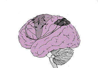
Fig. 2. Cortical projections involving the motor areas. (From (Berne RM, Levy MN,
used in order to detect the desired movement or intention.
Koeppen BM, Stanton BA. Physiology, Fourth edition , 1998).
3.2 Non-Invasive Signals
Non-invasive exploration of human brain functions has always been a central topic in
biomedical research. This is not only motivated by the high risk of invasive implantation
surgery but also because macroscopic information has inherent value due to the information
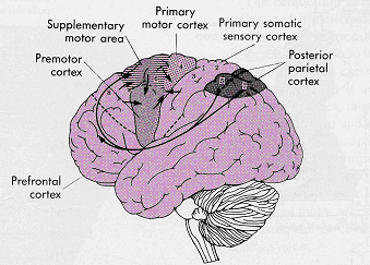
it provides on the motor command. Before any movement occurs, motor commands carried
by descending motor pathways must first be organized in the brain. The target of the
movement is identified by pooling sensory information in the posterior parietal cerebral
cortex (Jakson et al., 1999). This information is then transmitted to the supplementary motor
and premotor areas where a motor plan is developed. The plan includes information about
the specific muscles that need to be contracted, the strength of contraction, and sequence of
contraction. The motor plan is implemented by commands transmitted from the primary
motor cortex through the descending pathways. Successful execution of these motor
commands, however, depends on feedback provided to the motor cortex through the
ascending pathways to the somatosensory cortex as well as through the visual pathway.
One should also add that during both the planning and execution stages of a movement,
motor processing is also provided by 2 major control systems, the cerebellum and basal
ganglia (Figures 2 and 3).
In order to monitor the spatio-temporal evolution of the cortical activity within the human
brain, several methods make use of the electric potential and/or magnetic fields associated
with the intracellular current that flows within the active pyramidal cells of the cortex.
Surface electrodes can record electrical potential differences from a scalp surface leading to
what is called electroencephalography (EEG). Magnetoencephalography (MEG) makes use
of a superconducting quantum interference device (SQUID) magnetometer in order to
Fig. 3. Flow diagram showing the sequence of activity in the voluntary motor and
record the weak magnetic fields outside the head surface (Knuutila et al 1993). Moreover,
somatosensory feedback pathways. (From Berne RM, Levy MN, Koeppen BM, Stanton BA.
one goal in electric and magnetic recordings is to form an image of the electrical sources
Physiology, Fourth edition , 1998).
distributed across the cortex (Mosher et al., 1992) (Dale & Sereno, 1993).


Brain Imaging and Machine Learning for Brain-Computer Interface
61
3. Feature Extraction
Several measurement procedures have been used in modern BCI. As stated earlier, they can
be divided into two categories. Non invasive procedures include Electroencephalography
(EEG), Magnetoencephalography (MEG), functional magnetic resonance imaging (fMRI),
positron emission tomography (PET) and near infrared spectroscopy (NIRS).
Electrocorticography (ECoG), a method in which signals are recorded using intracranial
electrodes, is used as an invasive procedure to collect signals.
3.1 Spike Signals
The brain has a fascinating design consisting of a huge number of neurons that operate in
parallel and a distributed memory system formed of synapses. There are over 100 trillions of
synapses in the cerebral cortex. Each neuron is assumed to produce a unique and consistent
spike waveform which is difficult to detect. The duration of a spike is on average 1
millisecond and its peak-to-peak voltage is from 100 to 400 V. The spikes cannot be used
directly by the detection part of a BCI system. State of the art invasive BCI systems, start by
sorting the spike trains (Shenoy et al., 2006). The distribution of specific spike signals can be
Fig. 2. Cortical projections involving the motor areas. (From (Berne RM, Levy MN,
used in order to detect the desired movement or intention.
Koeppen BM, Stanton BA. Physiology, Fourth edition , 1998).
3.2 Non-Invasive Signals
Non-invasive exploration of human brain functions has always been a central topic in
biomedical research. This is not only motivated by the high risk of invasive implantation
surgery but also because macroscopic information has inherent value due to the information
it provides on the motor command. Before any movement occurs, motor commands carried
by descending motor pathways must first be organized in the brain. The target of the
movement is identified by pooling sensory information in the posterior parietal cerebral
cortex (Jakson et al., 1999). This information is then transmitted to the supplementary motor
and premotor areas where a motor plan is developed. The plan includes information about
the specific muscles that need to be contracted, the strength of contraction, and sequence of
contraction. The motor plan is implemented by commands transmitted from the primary
motor cortex through the descending pathways. Successful execution of these motor
commands, however, depends on feedback provided to the motor cortex through the
ascending pathways to the somatosensory cortex as well as through the visual pathway.
One should also add that during both the planning and execution stages of a movement,
motor processing is also provided by 2 major control systems, the cerebellum and basal
ganglia (Figures 2 and 3).
In order to monitor the spatio-temporal evolution of the cortical activity within the human
brain, several methods make use of the electric potential and/or magnetic fields associated
with the intracellular current that flows within the active pyramidal cells of the cortex.
Surface electrodes can record electrical potential differences from a scalp surface leading to
what is called electroencephalography (EEG). Magnetoencephalography (MEG) makes use
of a superconducting quantum interference device (SQUID) magnetometer in order to
Fig. 3. Flow diagram showing the sequence of activity in the voluntary motor and
record the weak magnetic fields outside the head surface (Knuutila et al 1993). Moreover,
somatosensory feedback pathways. (From Berne RM, Levy MN, Koeppen BM, Stanton BA.
one goal in electric and magnetic recordings is to form an image of the electrical sources
Physiology, Fourth edition , 1998).
distributed across the cortex (Mosher et al., 1992) (Dale & Sereno, 1993).
62
Biomedical Imaging
3.2.1 Electroencephalography
alert state of mind and can reach frequencies near 50 hertz during intense mental
The EEG is a recording of the rhythmic electrical activity that can be made from the cerebral
activity.
cortex via electrodes placed on the surface of the skull. In clinical neurology, EEG is
Delta (0.5-4 Hz): Delta waves are normal during drowsiness and early slow-wave
recorded from a grid of standard recording sites. EEG is recorded as a potential difference
sleep
between a signal or active electrode (electrode that records the activity at the site of interest
Theta (4-7 Hz): Theta waves arise from emotional stress, especially frustration or
on the surface of the skull) and a reference or indifferent electrode (e.g. electrode placed at
disappointment.
the ear lobe) (Westbrook, 2000). A conductive paste will be used to decrease contact
Mu (8-12 Hz): Mu waves are linked to cortical motor activity and have been
impedance and electrode migration (Westbrook, 2000).
associated with beta activity. Mu waves diminish with movement or the intention
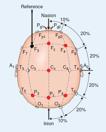
Different EEG standard exist and mainly differ in the position of the electrodes on the skull.
to move. They occupy the same frequency band as Alpha waves.
In the international 10-20 system EEG signals are recorded from a 59 electrodes placed on
Gamma (26-40 Hz): Gamma waves are considered to reflect the mechanism of
the skull as shown in Fig. 4 (Sajda et al., 2003). The signals are usually referenced to the left
consciousness.
mastoid.
These waves, especially Mu and Beta, have been used as features in several BCI systems. An
example of EEG waves is provided in Fig. 5.
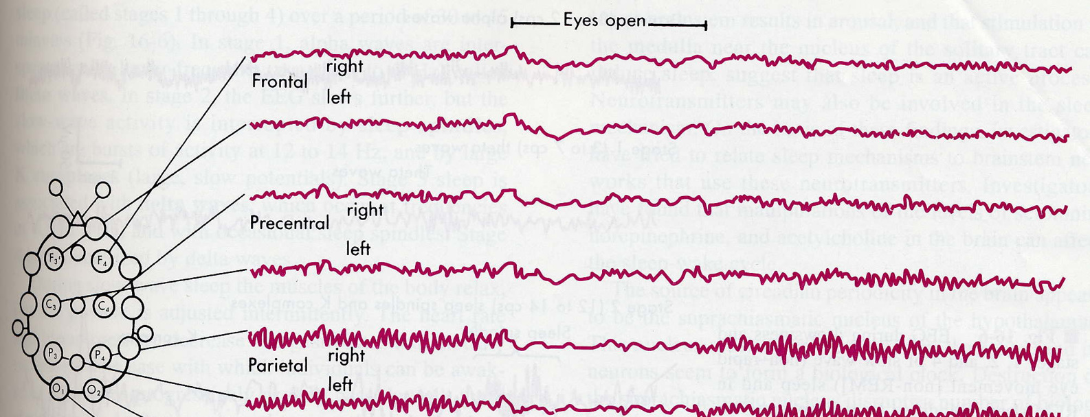
Fig. 5. EEG in a normal resting awake human. The recordings were made from eight
channels at the same time. The electrode positions are indicated. (From Berne RM, Levy
Fig. 4. The International 10-20 electrodes placement system (From Jasper HH. The ten-
MN, Koeppen BM, Stanton BA. Physiology, Fourth edition , 1998).
twenty electrode system of the international federation. In: Internal Federation of Societies
for Electroencephalography and Clinical Neurophysiology. Recommendations for the
The importance of the EEG resides in its ability to describe the activity on the cortex surface.
practice of clinical electroencephalography. Elsevier, 1983: 3-10).
Therefore, several techniques of brain imaging proposed the use of EEG in order to provide
a full image of the electrical activity on the surface of the cortex. Based on the EEG signals,
EEG patterns are characterized by the frequency and amplitude of the electrical activity
different sets of features can be derived. Classical features used in different BCI systems are
(Westbrook, 2000). The normal human EEG shows activity over the range of 1-30 Hz with
first briefly described. Brain Imaging based features are then provided in detail.
amplitudes in the range of 20-100 V. The observed frequencies have been divided into
several groups:
3.2.2 EEG-Based Classical Features
Alpha (8-13Hz): Alpha waves of moderate amplitude are typical of relaxed
Several features have been classically derived from the EEG data and used by the decoding
wakefulness and are most prominent over the parietal and occipital sites.
algorithm (Hammon & de Sa, 2007). The key idea is to derive some relevant and robust
Beta (13-30 Hz): Lower amplitude beta activity is more prominent in frontal areas
and over other regions during intense mental activity. They are associated with an

Brain Imaging and Machine Learning for Brain-Computer Interface
63
3.2.1 Electroencephalography
alert state of mind and can reach frequencies near 50 hertz during intense mental
The EEG is a recording of the rhythmic electrical activity that can be made from the cerebral
activity.
cortex via electrodes placed on the surface of the skull. In clinical neurology, EEG is
Delta (0.5-4 Hz): Delta waves are normal during drowsiness and early slow-wave
r