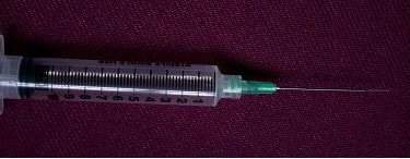
As a sample, a needle probe designed for the OCT imaging in this work is shown in Fig 13
since the mechanical strength at the interface was similar to that of the untreated fiber. The
(a). The lens and the uncoated portion of the SMF are protected in a transparent inner
desired focused beam profile was obtained by tailoring the length of the fiber spacer and
catheter (OD 0.49 mm) shown in Fig. 13 (b, c). The buffered portion of the fiber is attached to
parameters of fiber lenses (length of GRIN fiber and diameter of the ball) based on the
an outer flexible catheter after the syringe (OD 1.4 mm), which is fastened onto a modified
theoretical results. We fabricated the different variations of the GRIN and ball fiber lens
syringe piston, while the transparent inner catheter is inserted into a 21 G (OD 0.81 mm)
modules with the different length of the fiber spacer and the different lens parameter. All
echogenic spinal needle (VWR, Mississauga, ON, Canada). After insertion into the tissue,
samples were listed in Table 3 with detailed information.
the needle can be drawn back while the optical probe stays inside of the tissue as shown in
Fig. 13 (b). The probe is then scanned axially inside the tissue driven by a linear scanner,
A beam profile measurement system (BeamView Analyzer, OR, USA) with an infrared
such that a two dimensional OCT image is formed. If a fiber GRIN lens is used, the size of
camera (Electrophysics, NJ, USA) and a Super Luminous Diode source (Covega, MD, USA)
the inner catheter could be as small as 0.4 mm because the diameter of the GRIN lens is
with 60nm 3dB bandwidth at 1310 nm center wavelength was used to characterize the beam
smaller than the fiber ball lens.
parameters of the lens system. A 40X JIS microscopic objective lens and a related objective
tube were attached to the input window of the camera to increase the image resolution. The
horizontal and vertical resolutions of the system were 1.0 m and 1.1 m, respectively. The
Full Range Swept-Source Optical Coherence
Tomography with Ultra Small Fiber Probes for Biomedical Imaging
47
2
distribution of light intensity at various distances along the direction of propagation after
n( r)
g
n
r
(11)
0 1
(
2 )
2
the lens was accurately measured by the beam profile system. Working distance, depth of
focus, 1/e2 spot size, and Gaussian fitting were analyzed from the measured intensity
where r is the radial position from the axis, n
distribution. The results demonstrated in this work are all in the air medium.
0 is refractive index on the lens axis, g is the
gradient constant. The pitch, p = 2 /g, is the spatial period of the ray trajectory. For
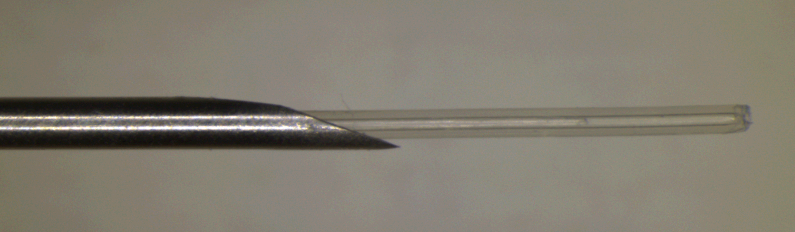
modeling of the ball fiber, the Standard Surface type in ZEMAX is employed. Fig. 12 (a) and
In addition, after characterization of the lens, a beam director could be attached to the lens
(b) show the ZEMAX ray trace layout of the GRIN and ball fiber lenses, respectively, with
for a side-view probe. The different attaching methods were used for the two lenses. For the
their scanning electron micrographs in the insets. The working distance, depth of field and
GRIN lens, a fiber spacer was fusion-spliced to the finished lens end as a beam director by
spot size were calculated in ZEMAX using the Gaussian beam theory. The theoretical results
polishing the end of the fiber spacer to a 45 degrees angle and coating the polished surface
will be shown and discussed in comparison with the experimental results below.
with a total reflection film. This then allowed the beam to be reflected at a 90 degrees angle
creating a side-view probe. For the ball lens probe, the beam can be 90-110 degree reflected
by a 45-50 degree polished face on the ball lens by the total internal reflection. Insets of Fig.
4.2 Fabrication Method of the fiber probes
12 (a) and (b) show the typical scan electron microscope (SEM) pictures of the GRIN and ball
The GRIN and ball fiber lens probes were made from a standard Corning SMF-28 single
fiber lens tip fused with beam directors, respectively. The fiber lens tip together with a
mode fiber as the principal light guide, a fiber spacer and a GRIN or a ball fiber lens as the
tubing system and a connected linearly scanning or 360 degrees rotated motor could be built
focusing lens. For the GRIN lens probe, a fiber spacer with same outer diameter (0.125 mm)
as an endoscope, or catheter, or a needle probes. The diameter of these probes could be as
as SMF-28 was fusion-spliced via arc welds to the Corning SMF-28 and then accurately
small as 0.4 mm which is best suitable for internal in situ and in vivo biomedical imaging,
cleaved to a theoretically-determined length. A GRIN fiber was then fusion-spliced to the
diagnostic, guided surgery, and treatment with a minimal invasion.
cleaved fiber spacer and precisely cleaved at a pre-calculated length to generate a desired
beam-distance profile (i.e., working distance, depth of field, and spot size). For a short
working distance probe, the section of the fiber spacer was omitted resulting in a simple
1mm
(a)
(b)
fabrication process. For the ball lens probe, a fiber spacer was fusion-spliced via arc welds to
the Corning SMF-28 and then accurately cleaved to a theoretically-determined length plus
extra 0.2 mm. The tip of the fiber spacer then was fused via arc welds to a perfect ball shape
by inputting an appropriate fusion setting. To ensure minimum back-reflection for both
probes, the indexes of the fiber spacer and the center of GRIN fiber were matched to the core
index of the SMF.
10mm
We used a conventional low cost off-the-shelf optical multi-mode GRIN fibers as the GRIN
(c)
0.4mm
lens, which has 0.1 mm core size, 0.14 mm outer diameter, a core refractive index n 0 = 1.487,
Fig. 13. OCT side-view needle probe showing the tubing and angle-polished ball lens. (a)
and a gradient constant g = 3.76 at 1300 nm (Prime Optical Fiber Corp., Taiwan). The fiber
needle probe. (b) retracted needle tip with protective tubing. (c) protective tubing and
spacers (Prime Optical Fiber Corp., Taiwan) are made of pure silica without a core. Fusion-
exposing the lens.
splicing was processed using an Ericsson FSU 995 fusion-splicer and an EFC11 fiber cleaver
(3SAE Technologies, TN, USA). The spliced interfaces produced minimum back-reflections
As a sample, a needle probe designed for the OCT imaging in this work is shown in Fig 13
since the mechanical strength at the interface was similar to that of the untreated fiber. The
(a). The lens and the uncoated portion of the SMF are protected in a transparent inner
desired focused beam profile was obtained by tailoring the length of the fiber spacer and
catheter (OD 0.49 mm) shown in Fig. 13 (b, c). The buffered portion of the fiber is attached to
parameters of fiber lenses (length of GRIN fiber and diameter of the ball) based on the
an outer flexible catheter after the syringe (OD 1.4 mm), which is fastened onto a modified
theoretical results. We fabricated the different variations of the GRIN and ball fiber lens
syringe piston, while the transparent inner catheter is inserted into a 21 G (OD 0.81 mm)
modules with the different length of the fiber spacer and the different lens parameter. All
echogenic spinal needle (VWR, Mississauga, ON, Canada). After insertion into the tissue,
samples were listed in Table 3 with detailed information.
the needle can be drawn back while the optical probe stays inside of the tissue as shown in
Fig. 13 (b). The probe is then scanned axially inside the tissue driven by a linear scanner,
A beam profile measurement system (BeamView Analyzer, OR, USA) with an infrared
such that a two dimensional OCT image is formed. If a fiber GRIN lens is used, the size of
camera (Electrophysics, NJ, USA) and a Super Luminous Diode source (Covega, MD, USA)
the inner catheter could be as small as 0.4 mm because the diameter of the GRIN lens is
with 60nm 3dB bandwidth at 1310 nm center wavelength was used to characterize the beam
smaller than the fiber ball lens.
parameters of the lens system. A 40X JIS microscopic objective lens and a related objective
tube were attached to the input window of the camera to increase the image resolution. The
horizontal and vertical resolutions of the system were 1.0 m and 1.1 m, respectively. The
48
Biomedical Imaging
Length of
Fiber Lens
Measured Beam Properties
obtain larger working distance, a fiber spacer has to be used. In these cases, the working
Sp.#
Fiber
Working
Depth of
Spot
distance varies sharply with the length of GRIN fiber for the GRIN fiber lens and with the
Spacer
Type/Diameter
Length
Distance
Field
Size
diameter of the ball for the ball fiber lens, but it varies less sharply with the length of the
(mm)
(m)
(mm)
(mm)
(mm)
(m)
fiber spacer. The working distances have saturated values for each case. By compensating
1
0
GRIN100/140
0.60
0.18
0.16
13
the working distance with the depth of field and the spot size, the optimized parameters (i.e.
2
0
GRIN100/140
0.55
0.20
0.30
16
0.9 – 1.2 mm working distance, 0.9 – 1.1 mm depth of filed, and <30 m spot size) are not at
3
0
GRIN100/140
0.52
0.28
0.50
22
the position of the largest working distance, instead, the optimized positions are around 0.17
4
0
GRIN100/140
0.50
0.38
0.60
23
mm length of the GRIN fiber with 0.48 mm length of fiber spacer for GRIN fiber lens and 0.3
5
0
GRIN100/140
0.48
0.41
0.85
25
mm diameter of ball and 0.62 mm length of fiber spacer for ball fiber lens. The results of the
6
0
GRIN100/140
0.46
0.40
1.30
30
experimental results as shown in Fig. 14 and Table 3 indicated that the ZEMAX numerical
optical design software were in a good agreement with the experimental results. We
7
0
GRIN100/140
0.45
0.38
1.45
32
obtained the working distance of 1.0 mm, the depth of field of 0.95 mm, and the spot size of
8
0.48
GRIN100/140
0.17
1.00
0.95
28
28 m from a GRIN fiber lens module (sample #8) and the working distance of 1.2 mm, the
9
0.48
GRIN100/140
0.16
1.10
1.5
35
depth of field of 1.1 mm, and the spot size of 27 m from a ball fiber lens module (sample
10
0.48
GRIN100/140
0.145
1.20
1.8
41
#14).
11
0.48
GRIN100/140
0.14
1.05
2.0
45
12
0.52
Ball Lens/300
~
1.00
3.6
50
Length of Fiber Space (mm)
Length of
Fiber Space
13
0.55
Ball Lens/300
~
1.4
2.1
45
Length of Fiber Space
0.0
0.2
0. 4 0.6 0.8
0.0
0.2
0. 4
0.6
0.8
0.0
0.2
14
0.62
Ball Lens/300
~
1.20
1.1
27
0.4
0.6
0.8
2.0
)m
4
60
15
0.70
Ball Lens/300
~
1.00
0.5
20
)
1.5
m 3
)
16
0.74
Ball Lens/300
~
0.90
0.33
16
40
istance (m 1.0
d (mel
Table 3. Structures of the various fiber lenses with measured beam properties.
2
of Fih
20
0.5
1
Spot Size (m
Dept
4.3 Characterization Results of the fiber probes
orking DW 0.0
0
0
The measured results of the beam properties are listed in Table 3 along with detailed
0.0
0.2
0.4
0.6
0.8
0.0
0.2
0.4
0.6
0.8
0.0
0.2
0.4
0.6
0.8
Length of GRIN Fiber or
Length of GRIN Fiber or Diamter of Bal Lens (mm)
descriptions of the listed samples. For each sample, optical intensity distribution data on the
Diameter of Bal Lens (mm)
Length of GRIN Fiber or Diameter of Bal lens (mm)
radial (i.e. x and y) planes were collected along the beam propagation (i.e. optical axial z)
(a)
(b)
(c)
direction from the plane of the first half peak intensity (begin-plane), through the maximum
Fig. 14. Theoretical and experimental results of working distance (a), depth of field (b), and
intensity plane, i.e. focus plane (center-plane), to the second half peak intensity plane (end-
spot size (c) vs. length of GRIN fiber or diameter of the ball lens (bottom x axis), and length
plane). Beam properties including working distance, spot size, and depth of field were
of fiber spacer (top x axis), where, lines represent the theoretical results from ZEMAX at
analyzed by measured intensity distribution data with distance from the lens surface to the
1300 nm, amount them, dark doted line represent GRIN fiber lens without a fiber spacer,
focal plane, 1/e2 beam diameter at the focal plane, and the distance between the begin-plane
dark and light solid lines represent GRIN fiber lens with a constant length of fiber spacer
and the end-plane, respectively. The theoretical and experimental results of working
(0.48 mm) and a constant length of GRIN fiber (0.17 mm), respectively; dark and light dash
distance, depth of focus, and spot size of different variations vs. length of GRIN fiber or
lines represent ball fiber lens with a constant length of fiber spacer (0.62 mm) and a constant
diameter of the ball lens (bottom x-axis), and length of fiber spacer (top x-axis) are shown in
diameter of the ball (0.30 mm), respectively. The related experimental results were
Fig. 14 (a), (b), and (c), respectively, where, lines represent the theoretical results from
represented by the points.
ZEMAX at 1300 nm, amount them, dark doted line represent GRIN fiber lens without a fiber
spacer, dark and light solid lines represent GRIN fiber lens with a constant length of fiber
We found quality of the beam depends very much on the quality of the surface cleaving and
spacer (0.48 mm) and a constant length of GRIN fiber (0.17 mm), respectively; dark and light
the alignment of the fusion-splicing between the fiber spacer and the fiber lens. The high
dash lines represent ball fiber lens with a constant length of fiber spacer (0.62 mm) and a
quality beam is easier to obtain for the probe with the ball fiber lens because the ball is made
constant diameter of the ball (0.30 mm), respectively. The experimental results were
from the fiber spacer and there is no interface between the fiber spacer and the ball lens. By
represented by points, amount them, triangle points represent GRIN fiber lens and square
well controlling the cleaving and the fusion-splicing, we obtained high quality of beam for
points represent the ball lens.
the probe of the GRIN fiber lens as well. Fig. 15 shows measured and Gaussian-fitted 1/e2
intensity beam diameters along the axial distance z (zero is the position of the lens surface)
From the theoretical result shown in Fig. 14, short working distance (<0.4 mm) could be
at x (horizontal) and y (vertical) radial coordination in the distance range of depth of field
obtained by the GRIN fiber lens without fiber spacer shown as the dark dotted lines. To
for the samples #1, #3 and #8 with the GRIN fiber lenses as shown in Table 3.
Full Range Swept-Source Optical Coherence
Tomography with Ultra Small Fiber Probes for Biomedical Imaging
49
Length of
Fiber Lens
Measured Beam Properties
obtain larger working distance, a fiber spacer has to be used. In these cases, the working
Sp.#
Fiber
Working
Depth of
Spot
distance varies sharply with the length of GRIN fiber for the GRIN fiber lens and with the
Spacer
Type/Diameter
Length
Distance
Field
Size
diameter of the ball for the ball fiber lens, but it varies less sharply with the length of the
(mm)
(m)
(mm)
(mm)
(mm)
(m)
fiber spacer. The working distances have saturated values for each case. By compensating
1
0
GRIN100/140
0.60
0.18
0.16
13
the working distance with the depth of field and the spot size, the optimized parameters (i.e.
2
0
GRIN100/140
0.55
0.20
0.30
16
0.9 – 1.2 mm working distance, 0.9 – 1.1 mm depth of filed, and <30 m spot size) are not at
3
0
GRIN100/140
0.52
0.28
0.50
22
the position of the largest working distance, instead, the optimized positions are around 0.17
4
0
GRIN100/140
0.50
0.38
0.60
23
mm length of the GRIN fiber with 0.48 mm length of fiber spacer for GRIN fiber lens and 0.3
5
0
GRIN100/140
0.48
0.41
0.85
25
mm diameter of ball and 0.62 mm length of fiber spacer for ball fiber lens. The results of the
6
0
GRIN100/140
0.46
0.40
1.30
30
experimental results as shown in Fig. 14 and Table 3 indicated that the ZEMAX numerical
optical design software were in a good agreement with the experimental results. We
7
0
GRIN100/140
0.45
0.38
1.45
32
obtained the working distance of 1.0 mm, the depth of field of 0.95 mm, and the spot size of
8
0.48
GRIN100/140
0.17
1.00
0.95
28
28 m from a GRIN fiber lens module (sample #8) and the working distance of 1.2 mm, the
9
0.48
GRIN100/140
0.16
1.10
1.5
35
depth of field of 1.1 mm, and the spot size of 27 m from a ball fiber lens module (sample
10
0.48
GRIN100/140
0.145
1.20
1.8
41
#14).
11
0.48
GRIN100/140
0.14
1.05
2.0
45
12
0.52
Ball Lens/300
~
1.00
3.6
50
Length of Fiber Space (mm)