6. Digital Input & Output
On processors, there are many “digital” pins that can be used as inputs or outputs. by “digital” pins we mean the pin can be “one” or “zero”.
Important note: Static discharge from anything including the human body will damage the processor. You know how sometimes you touch someone or something and you feel a little electronic discharge? This little discharge is high enough to kill electronic circuits. Professionals use equipment and take precautions handling the static charges in their body. You may not have such equipment so just try to stay away from touching the circuit if you don't have to. You may also use an Anti-static wrist band.
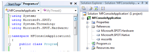
NETMF supports digital input and output pins through the “Microsoft.SPOT.Hardware” assembly and name space.
Go ahead and add the assembly and namespace like we learned before.
We are now ready to use the digital pins.
6.1. Digital Outputs
We know that a digital output pin can be set to zero or one. Note that one doesn't mean it is 1 volt but it means that the pin is supplying voltage. If the processor is powered off of 3.3V then state 1 on a pin means that there is 3.3V on the output pin. It is not going to be exactly 3.3V but very close. When the pin is set to zero then it's voltage is very close to zero volts.
Those digital pins are very weak! They can't be used to drive devices that require a lot of power. For example, a motor may run on 3.3V but you can NOT connect it directly to the processor's digital pin. That is because the processor's output is 3.3V but with very little power. The best you can do is drive a small LED or “signal” 1 or 0 to another input pin.
All FEZ boards have a LED connected to a digital pin. We want to blink this led.
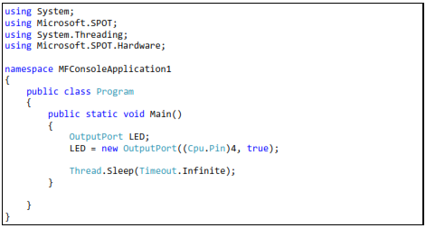
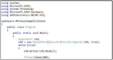
Digital output pins are controlled through an OutputPort object. We first create the object handler (reference), and then we make a new OutputPort object and assign it to our handler. When creating a new OutputPort object, you must specify the initial state of the pin, 1 or 0. The one and zero can be referred to high or low and also can be true for high and false for low. We will make the pin true (high) in this example to turn on our LED by default.
Here is the code using pin number 4, the FEZ Domino on-board LED.
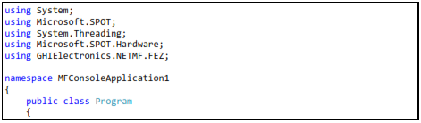
The GHI SDK ships with special assemblies containing the pin mapping of your device. For example, “FEZMini_GHIElectronics.NETMF.FEZ” is needed for FEZ Mini.
Now, modify the code by adding “using GHIElectronics.NETMF.FEZ” at the top of your program. Your device may have a different DLL.
Here is the code, this time using the FEZ pin enumeration class.
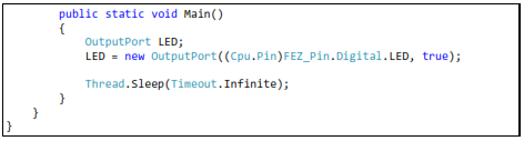
See how much easier that is? We really do not need to know where the LED is connected.
Run the program and observe the LED. It should be lit now. Things are getting more exciting!
Blink an LED
To blink an LED, we need to set the pin high and delay for some time then we need to set it low and delay gain. Its important to remember to delay twice. Why? It's because our eyes are too slow for computer systems. If the LED comes on and then it turns back off very fast, your eyes will not see that it was off for a very short time.
What do we need to blink a LED? ... We learned how to make a while-loop, we know how to delay, and we need to know how to set the pin high or low. This is done by calling the Write method on the OutputPort object. Note that you can't use “OutputPort.Write” This is very wrong because what output ports are you referring to? Instead, use “LED.Write” which makes complete sense.
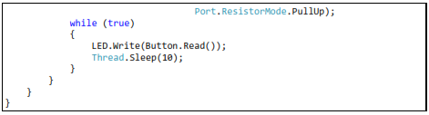
Here is the code to blink the on-board LED on FEZ Domino/Mini
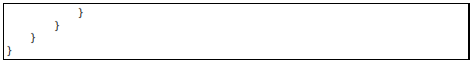
This is another way, a simpler way, to blink a LED.
Let's see if you can change the sleep time to make the LED blink faster or slower. Also, try to use a different value for its state so it is on for a long time and then it is off for a short time.
Important note: Never connect two output pins together. If they are connected and one is set to high and the other is set to low, you will damage the processor. Always connect an output pin to an input, driving circuit or a simple load like a LED.
6.2. Digital Inputs
Digital inputs sense if the state of its pin is high or low. There is a limitation on these input pins. For example, the minimum voltage on the pin is 0 volts. A negative voltage may damage the pin or the processor. Also, the maximum you can supply to a pin, must be less than the processor's power source voltage. All GHI Electronics boards use processors that run on 3.3V so the highest voltage the pin should ever see is 3.3V. This is true for ChipworkX and FEZ Hydra but not for EMX. EMX is 5V-tolerant. This means that even though the processor runs on 3.3V, it is capable of tolerating up to 5V on its inputs. Most digital chips that you would be interfacing with are 5V. Being 5V tolerant allows us to use any of those digital circuits with our processor.
Important note: 5V-tolerant doesn't mean the processor can be powered off of 5V. Always power it with 3.3V. Only the input pins can tolerate 5V on them.
The InputPort object is used to handle digital input pins. Any pin on the processor's GHI use can be an input or an output, but of course, not both! Unconnected input pins are called floating. You would think that unconnected input pins are low but this is not true. When a pin is an input and is not connected, it is open for any surrounding noise which can make the pin high or low. To take care of this issue, modern processors include an internal weak pull-down or pull-up resistor, that are usually controlled by software. Enabling the pull-up resistor will pull the pin high. Note that the pull-up resistor doesn't make a pin high but it pulls it high. If nothing is connected then the pin is high by default.
There are many uses for input ports but the most common is to connect it to a button or a switch. Many FEZ boards already includes an on-board button connected to the loader pin. The loader pin is used on power up to enter the boot loader but we can still use this pin at run-time. The button is enumerated as “LDR” or “Loader”.
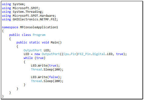
The button will connect between ground and the input pin. We will also enable the pull-up resistor. This means that the pin will be high (pull-up) when the button is not pressed and low (connected to ground) when the button is pressed.
We will read the status of the button and pass its state to the LED. Note that the pin is high when the button is not pressed (pulled-high) and it is low when the button is pressed. This means the LED will turn off when the button is pressed.
The code:
 ng
ng
6.3. Interrupt Port
If we want to check the status of a pin, we will always have to check its state periodically. This wastes the processor's time on something not important. You will be checking the pin, maybe, a million times before it is pressed! Interrupt ports allows us to set a method that will be executed when the button is pressed (when pin is low for example).
We can set the interrupt to fire on many state changes on the pin, when the pin is low or maybe when it is high. The most common use is the “on change”. The change from low to high or high to low creates a signal edge. The high edge occurs when the signal rises from low to high. The low edge happen when the signal falls from high to low.
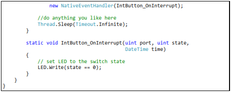
In the example below, I am using both edges so our method “IntButton_OnInterrupt” will automatically run whenever the state of our pin changes.
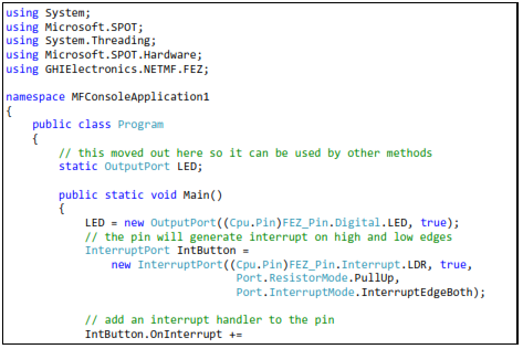
Note: Most but not all pins on the processor support interrupts.
6.4. Tristate Port
If we want a pin to be an input and output, what can we do? A pin can never be in and out simultaneously but we can make it output to set something and then make it input to read a response back. One way is to “Dispose” the pin. We make an output port, use it and then dispose it. Then we can make the pin an input and read it.
NETMF supports better options for this, through a Tristate port. Tristate means three states; that is input, output low and output high. One minor issue about tristate pins is; if a pin is set to output and then you set it to output again, we will receive an exception. One way to get around this is by checking the direction of the pin before changing it. The direction of the pin is its “Active” property where false means input and true is output. I personally do not recommend the use of Tristate ports unless absolutely necessary.
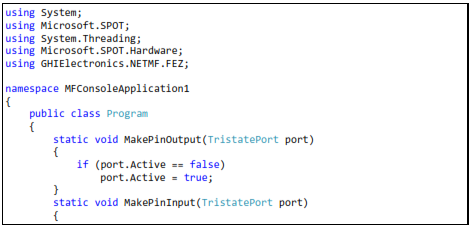
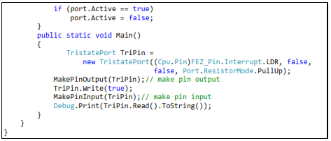
Note: Due to internal design, TristatePort will only work with interrupt capable digital pins.
Important Note: Be careful not to have the pin connected to a switch and then set the pin to output and high. This will damage the processor. I would say, for beginner applications you do not need a tristate port so do not use it until you are comfortable with digital circuits.