Everything we’ve done so far has been in two dimensions (2D). I did this deliberately to keep things simple. Now it’s time to make the jump to 3D (finally). It’s a big jump though, so brace yourself...
This tutorial isn’t intended to be an in-depth course on 3D geometry & mathematics, so I’ll keep this brief. Here, I’ll only cover the bare minimum needed to get started. If you want more detail (recommended), then read the “3D Transformations and Coordinate Systems” section of the Modern Graphics Programming Primer (https://keasigmadelta.com/graphics-primer).
To render 3D objects onto a 2D screen we must build a world of 3D objects, and then simulate a camera that views it. We’d also very much like to animate objects, and allow everything to move freely. This is achieved via a set of different coordinate systems. Transformation matrices are used to convert from one set of coordinates to another.
First up, is the model’s coordinate system (a.k.a., model space). A 3D model’s vertices are stored as vectors relative to a common origin (often the object’s centre). Why do this? Well, we can move the object around a 3D world by changing the model matrix (M), which transforms the points from model coordinates to world coordinates. We can also easily rotate the object about its own origin. Each model/object has its own local coordinates.
The world coordinate system is next. This is the global space that both 3D objects and the camera exist in. It’s the global reference that everything else is relative to.
Next, the camera has its own coordinates, known as view space, and it views the world relative to the camera’s origin. Objects & vertices are transformed from world to view space via the view matrix (V). This matrix is the inverse to what it would be for an object because it’s transforming from world space rather than to it (which is what the model matrix does).
Finally, objects are projected from view space onto the 2D screen via a projection matrix (P). Actually, it’s a bit more complicated than that (projection involves division), but you don’t need to know the details to use it.
There’s also a clip-space between the view space and screen. All you need to know about this is that it rejects everything that the camera can’t see (e.g., what’s behind and next to the camera).
The M, V, & P matrices can be multiplied together to form a single transformation from object to screen space:
ps = PVMpo
This is called the MVP matrix, although, as you can see above the matrices are multiplied in reverse order. It’s a little confusing, so here’s a good way to look at it. The vertex position po is on the far right, and it’s transformed first by the matrix to its immediate left (M), then the next (V), and the next (P).
Create a new project using the same method as in previous tutorials, and call it GLTutorial4. Next, copy the GLTutorial3 code: Shader.cpp|h, Texture.cpp|h, texture.vert|frag, and Main.cpp, and add them to the project. Also copy the texture file over (crate1_diffuse.png).
SDL_image also needs to be installed into the project (if you’re using Visual Studio and NuGet). So type the following into the NuGet Package Manager Console, and press enter:
Install-Package sdl2_image.v140
We need some kind of matrix/vector algebra library to perform the 3D transformations. While it is possible to write your own (done that myself), I recommend using a ready-made one. There are several well written open-source libraries available.
Here, we’ll be using a C++ matrix library called GLM (openGL Mathematics).2 It’s designed specifically for OpenGL. Visual Studio users can install by entering the following in the NuGet Package Manager Console:
Install-Package GLMathematics
For some reason Visual Studio can’t find the installed header files (at least on my system), so you may have to add the directory manually. Right-click on GLTutorial4, and select properties, select “VC++ Directories,” and add the GLM include directory to the “Include Directories” (Figure 11). Here’s the full include directories line I ended up with:
angle\include;..\packages\GLMathematics.0.9.5.4\build\native\include;$(IncludePath)

Figure 11: Adding the GLM includes manually.
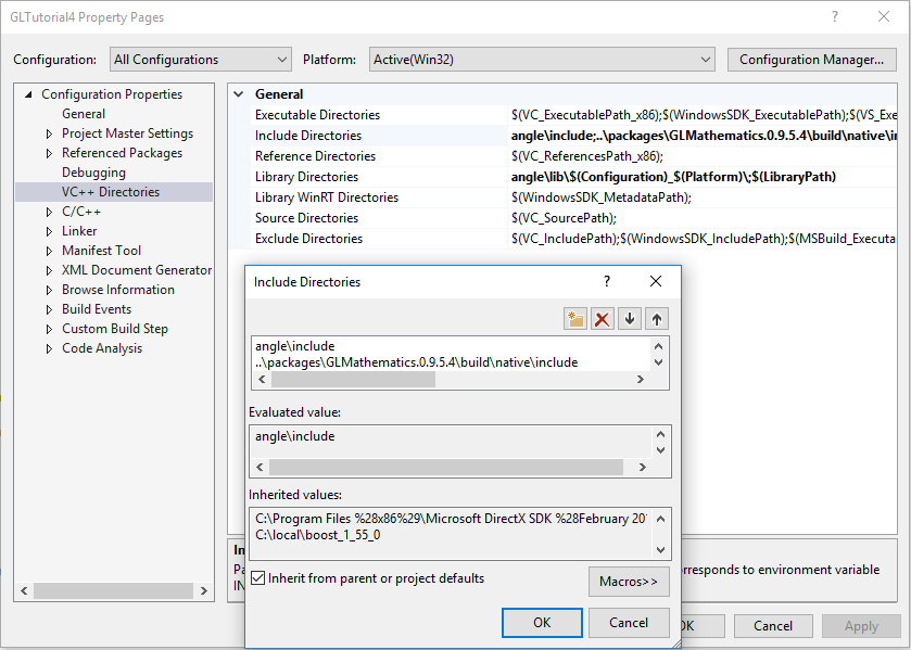
Figure 11: Adding the GLM includes manually.
Users of other platforms can download GLM from its project page: http://glm.g-truc.net/0.9.8/index.html
Installation is really easy because it’s a header only project (i.e., there’s nothing to compile). Simply copy the header files and add them to your project.
As explained in the theory section above, the 3D model’s vertices will be transformed from model space to view space, and then projected via the MVP matrix. Our existing texture.vert shader needs a few tweaks to be able to do this. First, the vertex position must be three dimensional, not 2D:
layout(location = 0) in vec3 vertPos;
Next, add an MVPMatrix uniform variable:
uniform mat4 MVPMatrix;
Finally, vertexPos must be (pre)multiplied by MVPMatrix to perform the transformation and projection:
gl_Position = MVPMatrix * vec4(vertPos, 1.0);
Here’s the resulting shader in full:
#version 300 es
layout(location = 0) in vec3 vertPos;
layout(location = 1) in vec2 vertTexCoord;
out vec2 texCoord;
uniform mat4 mvpMatrix;
void main() {
texCoord = vertTexCoord;
gl_Position = mvpMatrix * vec4(vertPos, 1.0);
}
The fragment shader (texture.frag) will work as-is. There is one more task, however; we need to get the MVPMatrix’s location so that we can set it later. Put the following code in main() underneath the code that binds texSampler to unit 0 (look for texSamplerUniformLoc):
// Get other uniform locations
GLint mvpMatrixLoc = glGetUniformLocation(shaderProg, "mvpMatrix");
if (mvpMatrixLoc < 0) {
SDL_Log("ERROR: Couldn't get mvpMatrix's location.");
return EXIT_FAILURE;
}
The Vertex structure also needs a 3D position to match the vertPos in the updated shader. So do that now:
/** Encapsulates the data for a single vertex.
* Must match the vertex shader's input.
*/
typedef struct Vertex_s {
float position[3];
float texCoord[2];
} Vertex;
NOTE: The position parameter is now an array of length 3 instead of 2.
OpenGL also needs to know about the new vertex position size, so find the glVertexAttribPointer() call for positionIdx, and update it to be a 3D vector:
glVertexAttribPointer(positionIdx, 3, GL_FLOAT, GL_FALSE,
sizeof(Vertex), (const GLvoid*)0);
NOTE: The one change is that the second parameter is now a 3.
We’re going to render a cube, so the vertices array needs to be updated. Here’s where things get a little more complicated. Last time we rendered a triangle-fan/quad. Now we’re going to render a 3D cube with multiple sides. This will be done with triangles.
We could store every triangle in the vertex array separately, but that would mean a lot of duplicate vertices (each vertex is used by 6 triangles). OpenGL allows us to avoid such duplication by using an index array. More about that later. First, here’s the big array of vertices:
// Create the 3D cube
float cubeSize_2 = 100.0f / 2.0f; // Half the cube's size
const Vertex vertices[] = {
// Front face
{ { -cubeSize_2, -cubeSize_2, cubeSize_2 },{ 0.0f, 0.0f } },
{ { cubeSize_2, -cubeSize_2, cubeSize_2 },{ 1.0f, 0.0f } },
{ { cubeSize_2, cubeSize_2, cubeSize_2 },{ 1.0f, 1.0f } },
{ { -cubeSize_2, cubeSize_2, cubeSize_2 },{ 0.0f, 1.0f } },
// Back face
{ { cubeSize_2, -cubeSize_2, -cubeSize_2 },{ 0.0f, 0.0f } },
{ { -cubeSize_2, -cubeSize_2, -cubeSize_2 },{ 1.0f, 0.0f } },
{ { -cubeSize_2, cubeSize_2, -cubeSize_2 },{ 1.0f, 1.0f } },
{ { cubeSize_2, cubeSize_2, -cubeSize_2 },{ 0.0f, 1.0f } },
// Left face
{ { -cubeSize_2, -cubeSize_2, -cubeSize_2 },{ 0.0f, 0.0f } },
{ { -cubeSize_2, -cubeSize_2, cubeSize_2 },{ 1.0f, 0.0f } },
{ { -cubeSize_2, cubeSize_2, cubeSize_2 },{ 1.0f, 1.0f } },
{ { -cubeSize_2, cubeSize_2, -cubeSize_2 },{ 0.0f, 1.0f } },
// Right face
{ { cubeSize_2, -cubeSize_2, cubeSize_2 },{ 0.0f, 0.0f } },
{ { cubeSize_2, -cubeSize_2, -cubeSize_2 },{ 1.0f, 0.0f } },
{ { cubeSize_2, cubeSize_2, -cubeSize_2 },{ 1.0f, 1.0f } },
{ { cubeSize_2, cubeSize_2, cubeSize_2 },{ 0.0f, 1.0f } },
// Top face
{ { cubeSize_2, cubeSize_2, -cubeSize_2 },{ 0.0f, 0.0f } },
{ { -cubeSize_2, cubeSize_2, -cubeSize_2 },{ 1.0f, 0.0f } },
{ { -cubeSize_2, cubeSize_2, cubeSize_2 },{ 1.0f, 1.0f } },
{ { cubeSize_2