The previous tutorial’s rendered image looks a little flat and lifeless (Figure 13). The real world has lights and shadows, and that’s what’s missing. So let’s add a light to our virtual world.
We’re going to add a single point light source. There are other light types (e.g., spotlights), but lets stick to the simplest one for now.
Try this: switch on a desk lamp and hold a ball under it. Notice how the object is bright where the lamp is shining on it, and in shadow on the opposite side. You might be thinking, “well duh, of course it’s like that.” Bear with me for a moment.
Look more closely at the ball. Notice how the ball is brightest where its surface is facing the lamp directly, and becomes darker as the surface’s angle shifts away from the lamp. It’s finally in shadow where the surface is perpendicular (90°) to the lamp.
Our lighting calculations need to simulate this effect. We’re going to use a simple diffuse colour model. It misses things such as shiny reflections, but it’s important to keep things simple. For more about lighting, have a look in the “Modern Graphics Programmer Primer’s” Lighting section.6
IMPORTANT: 3D lighting calculations involve vector algebra. If you have difficulty with the mathematics, then focus on the concepts behind them.
Surfaces with microscopic roughness tend to reflect light that hits it in all directions. This is called diffuse diffuse reflection.
As observed earlier, the brightness of that reflection depends on the angle between the surface and the oncoming light. To calculate the brightness, we need to know the direction the surface is facing (known as the surface normal n), and the direction to the light (l). This is shown in Figure 14.

Figure 14: Diffuse lighting depends on the surface normal and light direction.
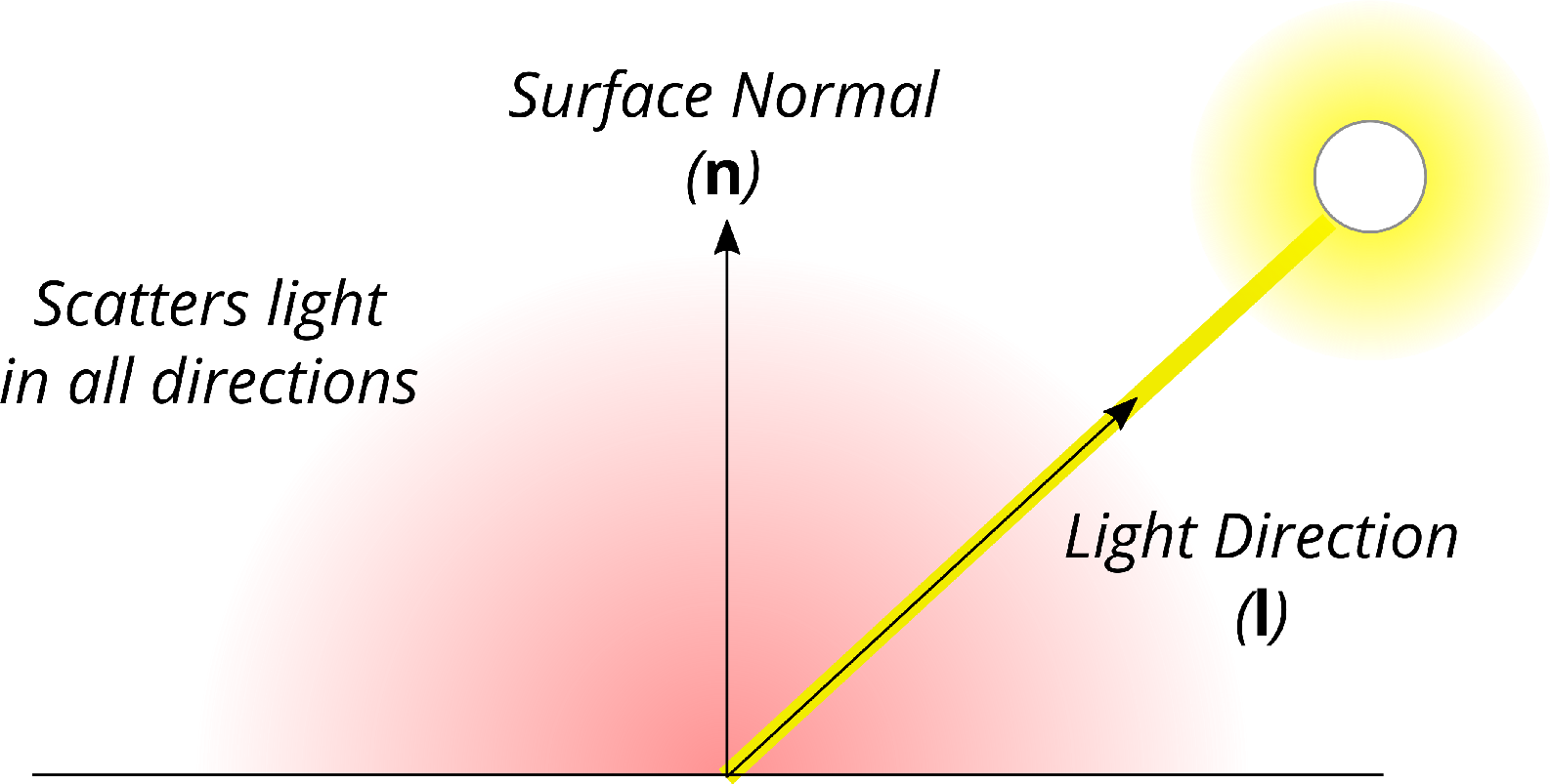
Figure 14: Diffuse lighting depends on the surface normal and light direction.
Mathematically, this is given by the following formula:
id= max(kdi(n·l), 0)
kd is the diffuse reflection constant, and id is the reflected light intensity, and (n·l) is the dot-product of the surface normal and light direction. The dot-product (n·l) is what models the reflected brightness dropping to 0 as the angle between the surface normal and light vectors increases.
The max() function is used to prevent the brightness from going negative when the surface faces away from the light. There’s no such thing as negative light.
The diffuse reflection formula above works well, but the side in shadow ends up being pitch black. This is uncommon in the real world because light can bounce many times from one object to another creating a sort of directionless background light (a.k.a., ambient light).
It’s theoretically possible to simulate this light using techniques such as raytracing. However, it’s very computationally intensive, so we’re going to use a simple approximation. And I mean, really simple.
We’re going to pretend that ambient light is a single constant. Real ambient light is much more complicated, but using a constant is really easy and gives surprisingly decent results (a lot of the time). Here’s the mathematical formula:
ia= kai
ka is the ambient reflection constant, and ia is the reflected ambient light intensity.
To get the final surface colour, we simply add the diffuse and ambient contributions together:
is = max(kdi(n·l), 0) + kai
is is the surface colour, as viewed by the eye/camera. Multiple lights can be handled simply by adding the diffuse, and ambient reflections from all lights together.
Phew, that was a lot of theory. Time to put it into practise. As with previous tutorials, create a new project (GLTutorial5), copy the files from the previous tutorial, and add them to the project.
With Visual Studio you’ll also have to install SDL_image and GLM again. Do this by entering the following in the NuGet Package Manager Console:
Install-Package sdl2_image.v140
Install-Package GLMathematics
Remember to also add the GLM include directory to the “Include Directories” the same way you did it last tutorial. For convenience, here’s the full include directories line I ended up with:
angle\include;..\packages\GLMathematics.0.9.5.4\build\native\include;$(IncludePath)
The vertex shader (texture.vert) needs some major additions. For starters, it needs to know the surface’s normal. Theoretically this could be calculated from the triangle vertices, but it’s much more efficient to precalculate them, and store them as a separate input:
layout(location = 2) in vec3 vertNormal;
The fragment shader needs a per-pixel copy of the surface normal and the light position vector:
out vec3 normal;
out vec3 lightVec;
There are also some new uniform variables. Firstly, the MVP matrix needs to be separated out. Next, normals need to be rotated by a special matrix, and the shader must know the light’s position:
uniform mat4 mvMat;
uniform mat4 normalMat;
uniform mat4 projMat;
uniform vec3 lightPos; // NOTE: position in view space (so after
// (being transformed by its own MV matrix)
In main(), calculating the position becomes a two-step process:
// Calc. the position in view space
vec4 viewPos = mvMat * vec4(vertPos, 1.0);
// Calc the position
gl_Position = projMat * viewPos;
Next, the surface normal is transformed into view space:
// Transform the normal
normal = normalize((normalMat * vec4(vertNormal, 1.0)).xyz);
Finally, the light position is calculated relative to the current position (i.e., relative to viewPos) :
// Calc. the light vector
lightVec = lightPos - viewPos.xyz;
That’s it for the vertex shader; the fragment shader takes over from here. For convenience, here’s the full shader code:
#version 300 es
layout(location = 0) in vec3 vertPos;
layout(location = 1) in vec2 vertTexCoord;
layout(location = 2) in vec3 vertNormal;
out vec2 texCoord;
out vec3 normal;
out vec3 lightVec;
uniform mat4 mvMat;
uniform mat4 normalMat;
uniform mat4 projMat;
uniform vec3 lightPos; // NOTE: position in view space (so after
// (being transformed by its own MV matrix)
void main() {
// Pass on the texture coordinate
texCoord = vertTexCoord;
// Calc. the position in view space
vec4 viewPos = mvMat * vec4(vertPos, 1.0);
// Calc the position
gl_Position = projMat * viewPos;
// Transform the normal
normal = normalize((normalMat * vec4(vertNormal, 1.0)).xyz);
// Calc. the light vector
lightVec = lightPos - viewPos.xyz;
}
The fragment shader has two new inputs that match the vertex shader’s new outputs:
in vec3 normal;
in vec3 lightVec;
It also needs two new uniforms for the diffuse colour (kdi), and ambient colour (kai). These uniforms combine the light colour and material reflectivity constants into one for efficiency:
uniform vec3 ambientCol; // The light and object's combined ambient colour
uniform vec3 diffuseCol; // The light and object's combined diffuse colour
Ambient lighting is the easiest to calculate:
// Base colour (from the diffuse texture)
vec4 colour = texture(texSampler, texCoord);
// Ambient lighting
vec3 ambient = vec3(ambientCol * colour.xyz);
Diffuse lighting is a bit more complicated:
// Calculate the light attenuation, and direction
float distSq = dot(lightVec, lightVec);
float attenuation = clamp(1.0 - invRadiusSq * sqrt(distSq), 0.0, 1.0);
attenuation *= attenuation;
vec3 lightDir = lightVec * inversesqrt(distSq);
// Diffuse lighting
vec3 diffuse = max(dot(lightDir, normal), 0.0) * diffuseCol * colour.xyz;
The light attenuation is how intense (bright) the light is, which reduces the farther away you are from the point light. I don’t want to explain the attenuation formula in detail. It’s designed to loosely approximate inverse square law,7 bust also gives the light a maximum reach radius (given by invRadiusSq, which is 1/radius2).
The final colour is calculated as follows:
// The final colour
// NOTE: Alpha channel shouldn't be affected by lights
vec3 finalColour = (ambient + diffuse) * attenuation;
fragColour = vec4(finalColour, colour.w);
Please compare the code carefully to the diffuse and ambient light formulae in the theory section. Make sure you can see how the code matches the formulae.
For convenience, here’s the shader code in full:
#version 300 es
#ifdef GL_ES
precision highp float;
#endif
in vec2 texCoord;
in vec3 normal;
in vec3 lightVec;
out vec4 fragColour;
uniform sampler2D texSampler;
uniform vec3 ambientCol; // The light and object's combined ambient colour
uniform vec3 diffuseCol; // The light and object's combined diffuse colour
const float invRadiusSq = 0.00001;
void main() {
// Base colour (from the diffuse texture)
vec4 colour = texture(texSampler, texCoord);
// Ambient lighting
vec3 ambient = vec3(ambientCol * colour.xyz);
// Calculate the light attenuation, and direction
float distSq = dot(lightVec, lightVec);
float attenuation = clamp(1.0 - invRadiusSq * sqrt(distSq), 0.0, 1.0);
vec3 lightDir = lightVec * inversesqrt(distSq);
// Diffuse lighting
vec3 diffuse = max(dot(lightDir, normal), 0.0) * diffuseCol * colour.xyz;
// The final colour
// NOTE: Alpha channel shouldn't be affected by lights
vec3 finalColour = (ambient + diffuse) * attenuation;
fragColour =